Fan and fan frame thereof

a technology of fan and frame, which is applied in the direction of positive displacement liquid engine, piston pump, liquid fuel engine, etc., can solve the problems of affecting the reliability and lifetime of the fan, reducing and heat dissipation becoming an important issue, so as to increase the air intake and increase the performance of the fan. , the effect of reducing the noise of air flowing through the mounting portions

Inactive Publication Date: 2008-09-25
DELTA ELECTRONICS INC
View PDF3 Cites 8 Cited by
  • Summary
  • Abstract
  • Description
  • Claims
  • Application Information

AI Technical Summary

Benefits of technology

[0009]In view of the foregoing, the present invention is to provide a fan with better performance and smaller noises and the fan frame thereof.
[0012]As mentioned above, the fan and the fan frame of the present invention utilize the auxiliary passages to increase the air intake. The auxiliary passages and the mounting portions of the main body are not communicated. Therefore, the airflow guided by the auxiliary passages is not affected by the mounting portions. Compared with the related art, the present invention can increase the performance of the fan and decrease noises when air flows through the mounting portions. In addition, the auxiliary passages are obliquely communicated with the main passage from the upper part of the main body. Therefore, the auxiliary airflow merges more smoothly with the main airflow without turbulence or vortices.

Problems solved by technology

This leads to instability and affects their reliability and lifetime.
Therefore, heat dissipation has become an important issue when designing new electronic products.
This causes turbulence or vortices that decrease the performance of the fan.

Method used


Image

  • Fan and fan frame thereof
  • Fan and fan frame thereof
  • Fan and fan frame thereof

Examples


Embodiment Construction

[0020]The present invention will be apparent from the following detailed description, which proceeds with reference to the accompanying drawings, wherein the same references relate to the same elements.

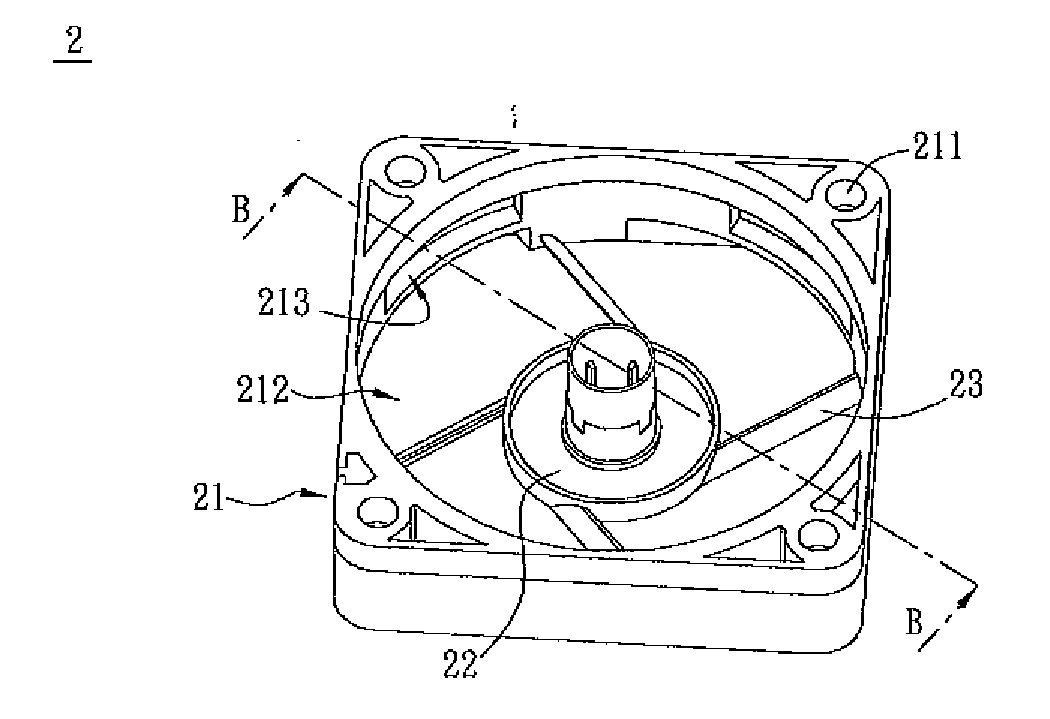
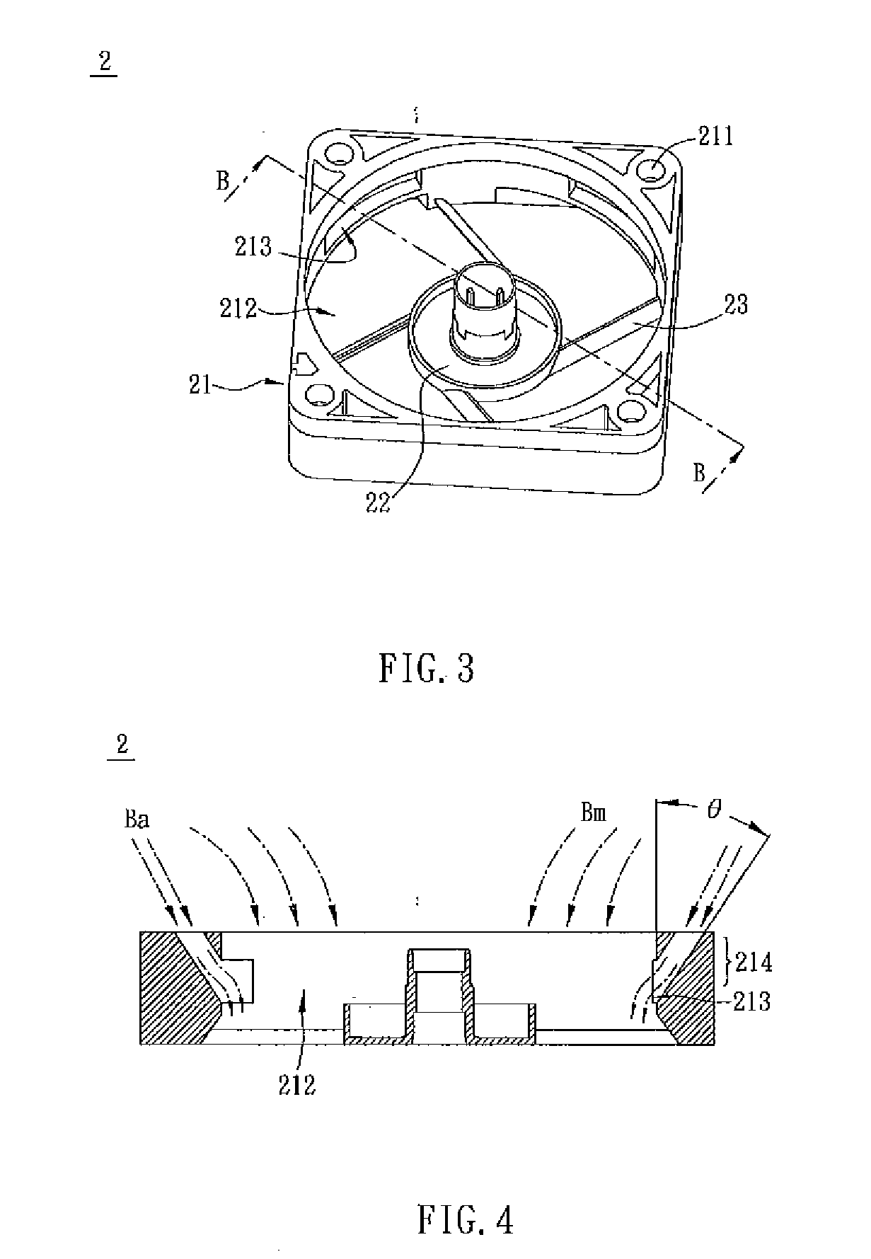
[0021]As shown in FIG. 3, a fan frame 2 according to an embodiment of the present invention includes a main body 21, a base 22 and at least one connecting element 23. In this embodiment, the fan frame 2 has several connecting elements 23. The base 22 is disposed in the central portion of the main body 21. Both ends of each connecting element 23 are respectively connected to the main body 21 and the base 22. The connecting elements 23, the base 22 and the main body 21 are integrally formed as a single unit.

[0022]The main body 21 has at least one mounting portion 211. In this embodiment, the main body 21 has four through holes as the mounting portions 211. A main passage 212 and at least one auxiliary passage 213 are disposed in the main body 21. In this embodiment, the main body 21 has...


PUM


Abstract

A fan frame of a fan includes a main body, a base and at least one connecting element. The main body has at least one mounting portion and at least one auxiliary passage, which are not communicated with each other. A main passage is disposed in the main body, and the auxiliary passage is obliquely communicated with the main passage from the upper part of the main body. The base is disposed in the central portion of the main body. The connecting element is disposed between the main body and the base. A fan including such fan frame is also disclosed.

Description

CROSS REFERENCE TO RELATED APPLICATIONS[0001]This Non-provisional application claims priority under 35 U.S.C. §119(a) on Patent Application No(s). 096110082, filed in Taiwan, Republic of China on Mar. 23, 2007, the entire contents of which are hereby incorporated by reference.BACKGROUND OF THE INVENTION[0002]1. Field of Invention[0003]The invention relates to a fan and a fan frame thereof, and, in particular, to a fan with an auxiliary passage and a fan frame thereof.[0004]2. Related Art[0005]As electronic products have better performance, higher operating frequencies, faster speeds and smaller sizes, their temperature also becomes higher. This leads to instability and affects their reliability and lifetime. Therefore, heat dissipation has become an important issue when designing new electronic products. Fans are common heat-dissipating devices used in electronic products.[0006]A conventional fan includes a fan frame, an impeller and a motor. The impeller and the motor are disposed ...

Claims


Application Information

Patent Timeline
Patent Type & Authority Applications(United States)
IPC IPC(8): F01D25/24F04B17/00
CPCF04D17/025F04D29/526F04D25/0613F04D29/684
Inventor LIN, CHENG-HUNGLU, CHAO-WEN
Owner DELTA ELECTRONICS INC
Why Eureka
Try Eureka