Device and method for monitoring the intake manifold pressure of an internal combustion engine

a technology of internal combustion engine and intake manifold, which is applied in the direction of machines/engines, electrical control, instruments, etc., can solve the problems of error persisting and recognition of achieve the effect of avoiding error in the operation of the intake and/or exhaust valve of at least one cylinder, reducing the probability of error, and improving the accuracy of the model

Inactive Publication Date: 2008-10-02
ROBERT BOSCH GMBH
View PDF15 Cites 39 Cited by
  • Summary
  • Abstract
  • Description
  • Claims
  • Application Information

AI Technical Summary

Benefits of technology

[0009]It is furthermore advantageous if the comparison of the measured signal for the intake manifold pressure with the reference signal for the intake manifold pressure is performed individually for each cylinder. In this way, an erroneous operation of the intake and / or exhaust valves or an error-free operation of the intake and / or exhaust valves of the cylinders may be implemented individually, i.e., for each cylinder.
[0010]It is furthermore advantageous if the comparison of the measured signal for the intake manifold pressure with the reference signal for the intake manifold pressure for a cylinder is allowed only at predefined, angle-synchronous points in time, which permit assigning the signal value of the reference signal to the corresponding cylinder. In this way, the cylinder-individual evaluation for an erroneous or error-free operation of the intake and / or exhaust valves is made possible, and signal components of the reference signal and / or of the measured signal for the intake manifold pressure originating from the different cylinders are effectively prevented from mutually influencing each other when the intake and / or exhaust valves of a certain cylinder are evaluated for errors during operation. It is thus ensured that the comparison of the measured signal for the intake manifold pressure with the reference signal for the intake manifold pressure may reliably be performed individually for each cylinder.
[0011]Another advantage results if an erroneous operation of the intake and / or exhaust valves of at least one cylinder is detected, if the measured signal for the intake manifold pressure exceeds the reference signal for the intake manifold pressure with respect to the at least one cylinder by more than a predefined value as a function of the predefined tolerance range, in particular for at least a predefined time period. In this way, the evaluation for erroneous or error-free operation of the intake and / or exhaust valves of the at least one cylinder is particularly easy. If the erroneous operation of the intake and / or exhaust valves of the at least one cylinder is detected only if the measured signal for the intake manifold pressure exceeds the reference signal for the intake manifold pressure with respect to the at least one cylinder by more than a predefined value as a function of the predefined tolerance range, in particular for the at least one predefined time period, the evaluation for the presence of an erroneous or error-free operation of the intake and / or exhaust valves is still particularly reliable and may not be affected by transient interference signals which have an effect for less than the predefined time period.
[0012]Another advantage results if an erroneous operation of the intake and / or exhaust valves of at least one cylinder is detected if the measured signal for the intake manifold pressure is outside a tolerance band formed as a function of the predefined tolerance range around the reference signal for the intake manifold pressure with respect to the at least one cylinder, in particular for at least a predefined time period. Due to the check performed in this case on both sides of the reference signal, a more precise statement regarding the type of the existing defect in the operation of the intake and / or exhaust valves may be made. This statement is particularly reliable if an erroneous operation of the intake and / or exhaust valves of the at least one cylinder is detected only if, for at least the predefined time period, the measured signal for the intake manifold pressure is outside a tolerance band formed as a function of the predefined tolerance range around the reference signal for the intake manifold pressure with respect to the at least one cylinder. In this case, the diagnosis of the operation of the intake and / or exhaust valves may not be distorted by a short-term interference signal which has an effect on the comparison of the measured signal with the reference signal for the intake manifold pressure for less than the predefined time period.
[0013]It is furthermore advantageous that, in the case where the measured signal for the intake manifold pressure deviates from the reference signal for the intake manifold pressure by more than the predefined tolerance range for less than a predefined time period, an erroneous operation of the intake and / or exhaust valves of the at least one cylinder is detected only if such a deviation is detected repeatedly with respect to the at least one cylinder. In this way, error phenomena in the operation of the intake and / or exhaust valves whose effect on the measured signal for the intake manifold pressure changes over time may also be recognized, i.e., when a deviation with respect to the reference signal by more than the predefined tolerance range exists for less than the predefined time period and subsequently decays again, but the error persists. This permits the measured signal for the intake manifold pressure to be investigated for cyclically decaying error phenomena and such error phenomena to be recognized. In this way, an error in the operation of the intake and / or exhaust valves may be recognized, which, due to its short-term effect on the measured signal for the intake manifold pressure for less than the predefined time period, would not be otherwise distinguishable from an arbitrary interference, for example, due to electrical interference with the measured signal for the intake manifold pressure.
[0014]Another advantage results if the reference signal is modeled on the basis of a container model which determines the variation of an intake manifold pressure over time on the basis of mass flows entering the intake manifold via an air supply and exiting the intake manifold into the at least one cylinder, in particular by taking into account intake manifold pressure fluctuations due to suction of the at least one cylinder. This permits the reference signal and thus the expected reference behavior to be ascertained in a particularly easy manner; the modeling may be refined and made more precise if the intake manifold pressure fluctuations due to the suction of the at least one cylinder are taken into account when modeling the reference signal.

Problems solved by technology

Such an erroneous operation of the intake and / or exhaust valves of the at least one cylinder may result because of at least one erroneously operating adjustment device for the intake and / or exhaust valves.
In this way, error phenomena in the operation of the intake and / or exhaust valves whose effect on the measured signal for the intake manifold pressure changes over time may also be recognized, i.e., when a deviation with respect to the reference signal by more than the predefined tolerance range exists for less than the predefined time period and subsequently decays again, but the error persists.
In this way, an error in the operation of the intake and / or exhaust valves may be recognized, which, due to its short-term effect on the measured signal for the intake manifold pressure for less than the predefined time period, would not be otherwise distinguishable from an arbitrary interference, for example, due to electrical interference with the measured signal for the intake manifold pressure.

Method used


Image

  • Device and method for monitoring the intake manifold pressure of an internal combustion engine
  • Device and method for monitoring the intake manifold pressure of an internal combustion engine
  • Device and method for monitoring the intake manifold pressure of an internal combustion engine

Examples


Embodiment Construction

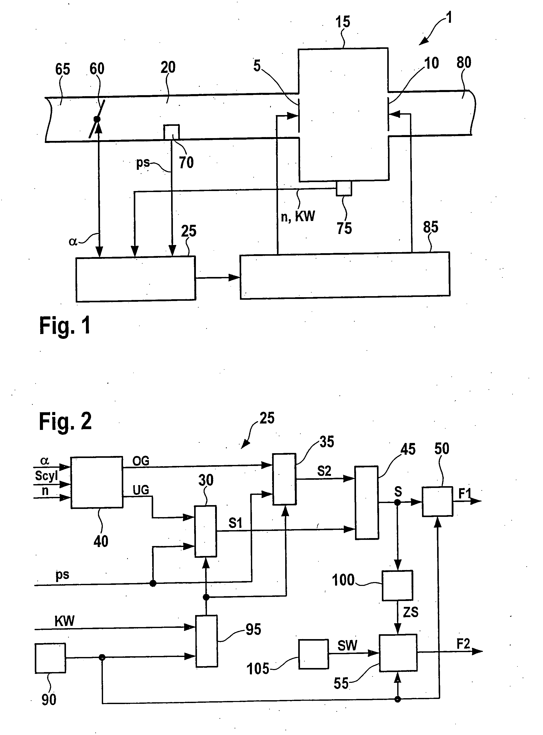
[0020]FIG. 1 shows an internal combustion engine 1, which may be designed as a gasoline engine or a diesel engine, for example. In the following it will be assumed, for example, that internal combustion engine 1 is designed as a gasoline engine. Internal combustion engine 1 includes one or more cylinders 15, only one of which is shown in FIG. 1 as an example. Air is supplied to a combustion chamber of cylinder 15 from an intake manifold 20 via one or more intake valves 5. Fuel is also supplied to the combustion chamber, the air / fuel mixture being ignited in the combustion chamber of cylinder 15 by a spark plug. The exhaust gas formed by the combustion of the air / fuel mixture is expelled into an exhaust tract 80 via one or more exhaust valves 10. Fresh air is supplied into intake manifold 20 via an air supply 65 and a throttle valve 60. Intake manifold pressure ps is detected with the aid of an intake manifold pressure sensor 70 in intake manifold 20. The signal, measured with the ai...


PUM


Abstract

A method and a device for monitoring the intake manifold pressure of an internal combustion engine in which a measured signal for the intake manifold pressure is compared with a reference signal for the intake manifold pressure. For a deviation of the measured signal for the intake manifold pressure from the reference signal for the intake manifold pressure, a tolerance range is predefined for error-free operation of the intake and/or exhaust valves of at least one cylinder of the internal combustion engine. A check is made whether the measured signal for the intake manifold pressure deviates from the reference signal for the intake manifold pressure by more than a predefined tolerance range. In this case an erroneous operation of the intake and/or exhaust valves is detected; otherwise an error-free operation of the intake and/or exhaust valves is detected.

Description

CROSS-REFERENCE[0001]This application claims the benefit under 35 U.S.C. §119 of German Application No. 102007013252.4 filed on Mar. 20, 2007, which is expressly incorporated herein by reference in its entirety.FIELD OF THE INVENTION[0002]The present invention relates to a method and a device for monitoring the intake manifold pressure of an internal combustion engine.BACKGROUND INFORMATION[0003]German Patent Application No. DE 103 00 593 A1 describes a method and a device for operating an internal combustion engine in which the intake manifold pressure of the internal combustion engine is monitored in such a way that in at least one operating state of the internal combustion engine when the exhaust gas recirculation is activated, a first intake manifold pressure in a first position of at least one control element in the exhaust tract and a second intake manifold pressure in a second position of the at least one control element in the exhaust tract are ascertained. The function of t...

Claims


Application Information

Patent Timeline
Patent Type & Authority Applications(United States)
IPC IPC(8): G01M15/09
CPCF02D41/221F02D2041/001F02D2200/0406Y02T10/40F02D28/00F02D41/02F02D41/06F02D41/22
Inventor HARTMANN, DIRKMALLEBREIN, GEORGMEZGER, WERNERBARBIER, HENRIMANNAL, SOENKE
Owner ROBERT BOSCH GMBH
Why Eureka
Try Eureka