Mass airflow sensing system including resistive temperature sensors and a heating element

Inactive Publication Date: 2008-10-02
HONEYWELL INT INC
View PDF20 Cites 20 Cited by
  • Summary
  • Abstract
  • Description
  • Claims
  • Application Information

AI Technical Summary

Benefits of technology

[0014]It is further aspect of the present invention to provide for a s

Problems solved by technology

Previous full Wheatstone bridge configurations, however, also often incur a low signal to noise ratio, particularly for very high or very low flow rates.
A low sign

Method used


Image

  • Mass airflow sensing system including resistive temperature sensors and a heating element
  • Mass airflow sensing system including resistive temperature sensors and a heating element
  • Mass airflow sensing system including resistive temperature sensors and a heating element

Examples


Embodiment Construction

[0022]The particular values and configurations discussed in these non-limiting examples can be varied and are cited merely to illustrate at least one embodiment and are not intended to limit the scope thereof.

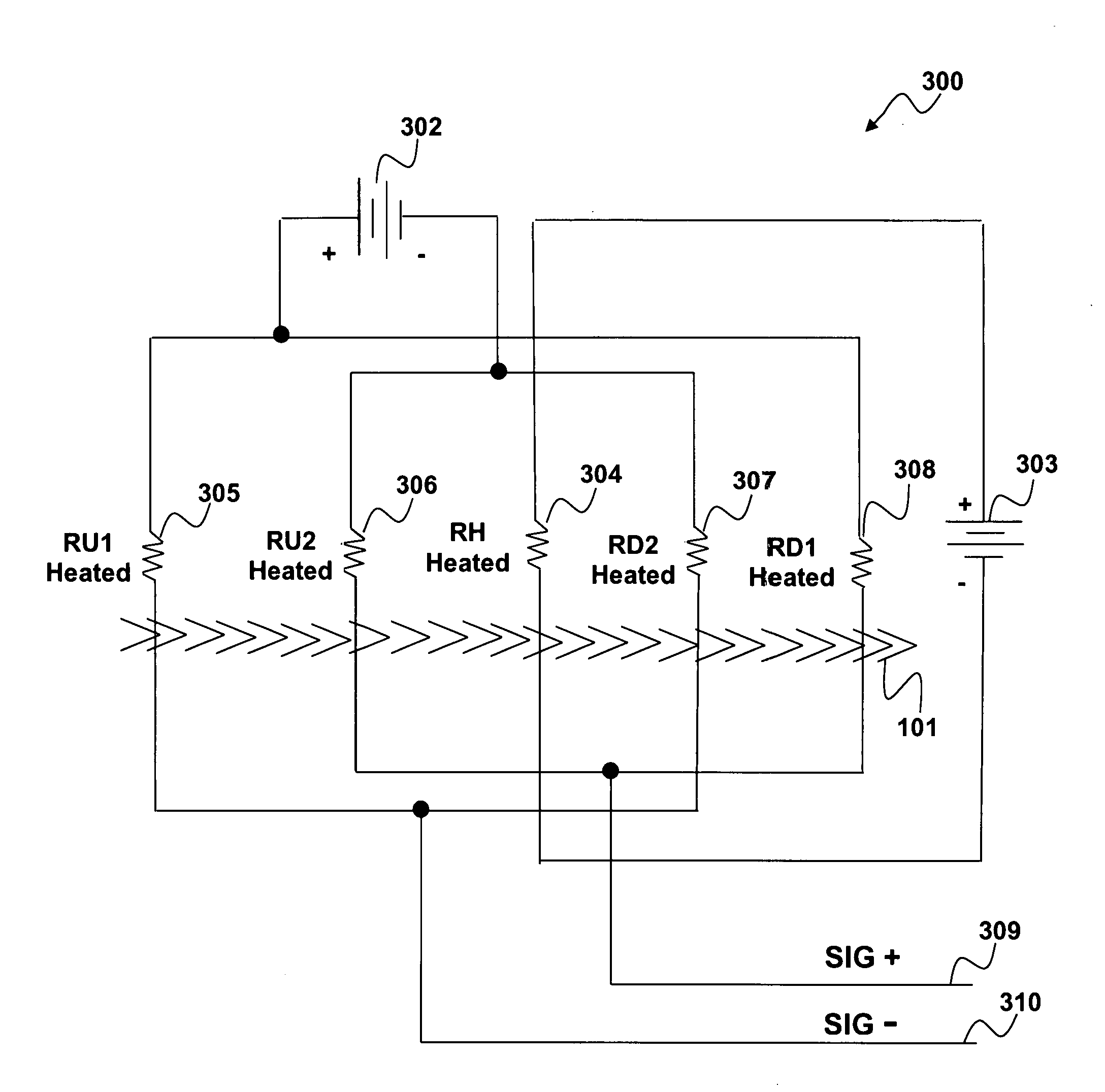
[0023]FIG. 3 illustrates a system 300 by which heating the sense resistors and heating a central element to sense mass flow, which can be implemented in accordance with a preferred embodiment. This system as illustrated is beneficial and shows how to eliminate the problems that were associated with this approach. The temperature sense resistors RU1304, RU2305, RD1308, and RD2307 are self heated by applying power to them. The sensing power supply 302 and heater power supply 303 are external excitation sources. Self heating increases the temperature of resistors in the sensing system when power is applied to them by power supply 302. The central heating element RH 304 is also heated when power by power supply 303. As mass air / liquid flows in a direction from left to right as indi...


PUM


Abstract

A mass airflow sensor is disclosed that includes a heating element comprising an upstream side and a downstream side. Two resistive temperature sensors are placed on each side of the heating element and assuming mass air/liquid flows in a direction from left to right. The resistors are configured electrically in a Wheatstone bridge configuration. A regulated voltage is applied across the mass flow sensing, Wheatstone bridge. The regulated voltage is set high enough to produce self-heating effects on the sensing bridge. The central heating element will also be heated. As mass air/liquid flows across the temperature sensors and the heating element, the upstream (RU1 and RU2) resistors are cooled and the downstream (RD1 and RD2) resistors are heated. The resistance in the resistive temperature sensors changes with temperature creating a differential voltage signal proportional to the regulated voltage applied to the sensing Wheatstone bridge and rate of mass air/liquid flow.

Description

TECHNICAL FIELD[0001]Embodiments are generally related to sensing devices and components. Embodiments are also related to mass fluid flow sensors. Embodiments are additionally related to resistive temperature sensors used to detect mass airflow.BACKGROUND OF THE INVENTION[0002]Sensors are used in a variety of sensing applications, such as, for example, detecting and / or quantifying the composition of matter, detecting and / or quantifying the presence of a particular substance from among many substances, and detecting and / or quantifying a mass flow rate of fluid (e.g., in air liquid form). The industrial, commercial, medical, and the automotive industries in particular require many ways to quantify the amount of gaseous and liquid mass flow rates. For example, in the medical industry, an airflow sensor is often employed to monitor and / or control a patient's breathing. Two examples of this include sleep apnea devices and oxygen conserving devices. Similarly, airflow sensors are often em...

Claims


Application Information

Patent Timeline
IPC IPC(8): G01F1/69
CPCG01F1/69G01F1/698G01F1/699
Inventor DMYTRIW, ANTHONY M.BECKE, CRAIG S.
Owner HONEYWELL INT INC
Why Eureka
Try Eureka