Vehicle brake apparatus

Active Publication Date: 2008-10-02
AUTOLIV NISSIN BRAKE SYST JAPAN CO LTD
View PDF8 Cites 23 Cited by
  • Summary
  • Abstract
  • Description
  • Claims
  • Application Information

AI Technical Summary

Benefits of technology

[0006]The invention has been made in view of the situations, and an object thereof is to provide a vehicle brake apparatus including a pressure regulating valve unit which is adapted to be applied to m

Problems solved by technology

Since this configuration makes the construction of the pressure regulating valve unit complex and also permits only a pressure regulation at a predetermined pressure in response to the input of brake application effort, when attempting to apply this very brake system to other model lines each having

Method used


Image

  • Vehicle brake apparatus
  • Vehicle brake apparatus
  • Vehicle brake apparatus

Examples


Example

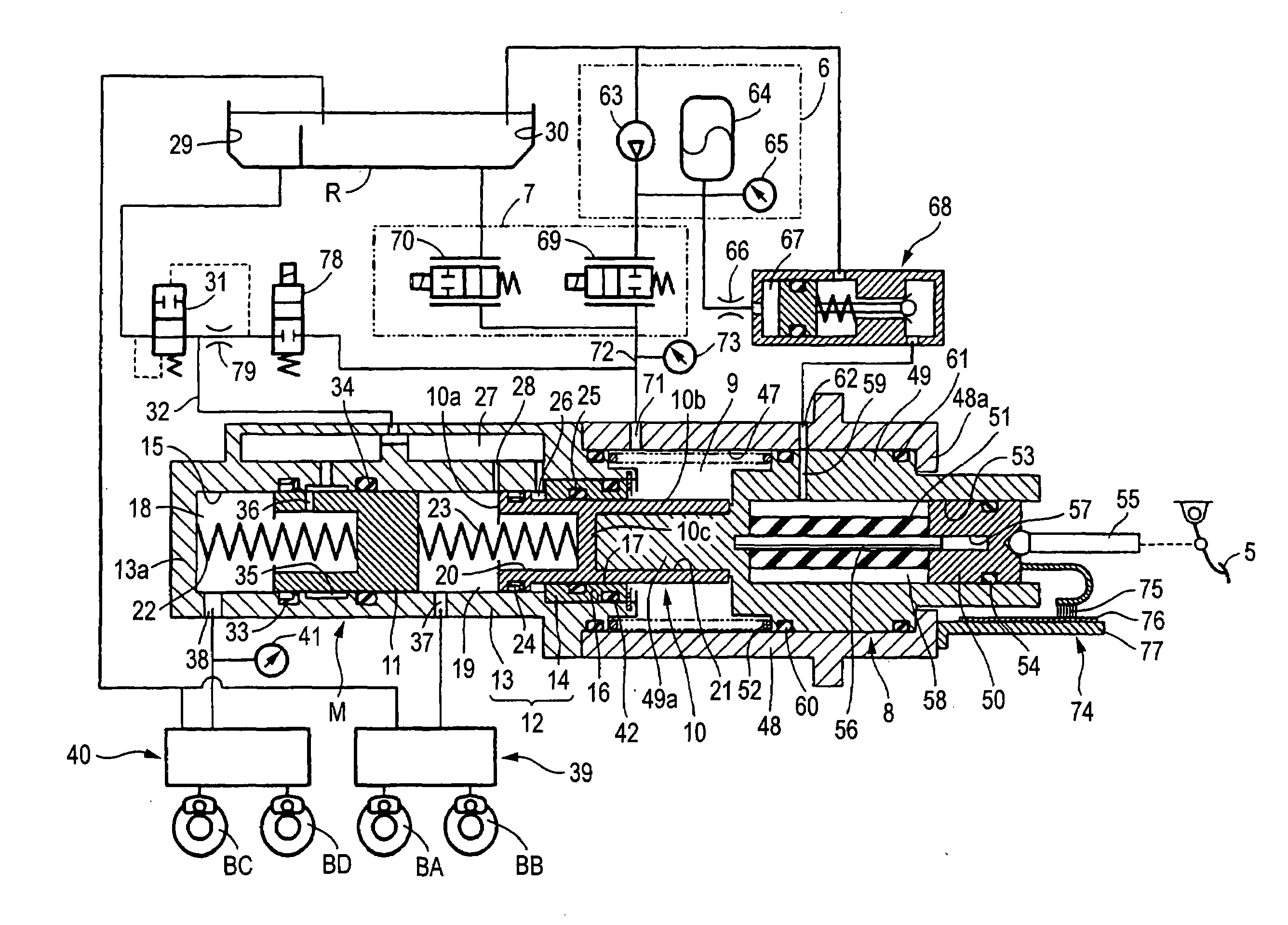
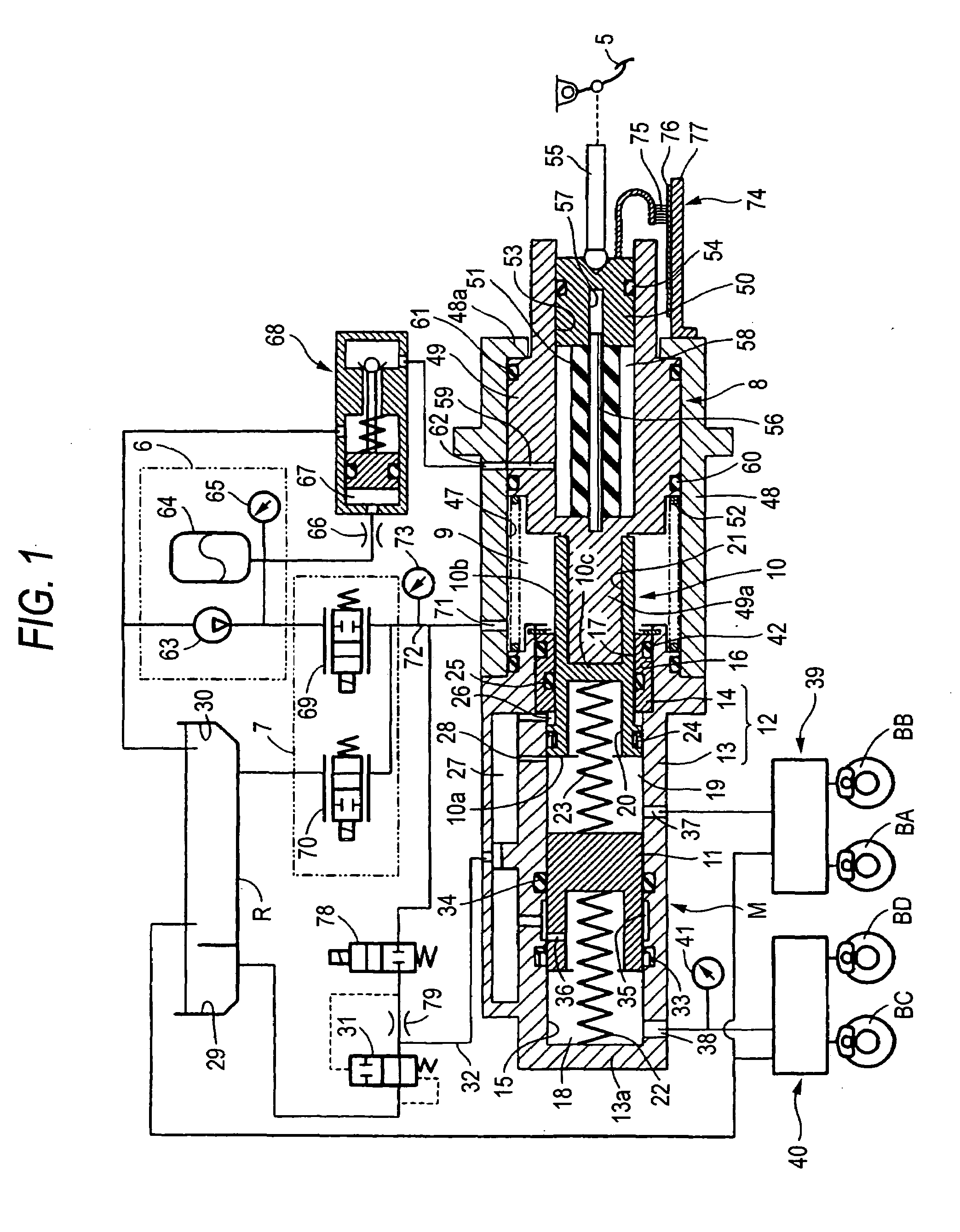
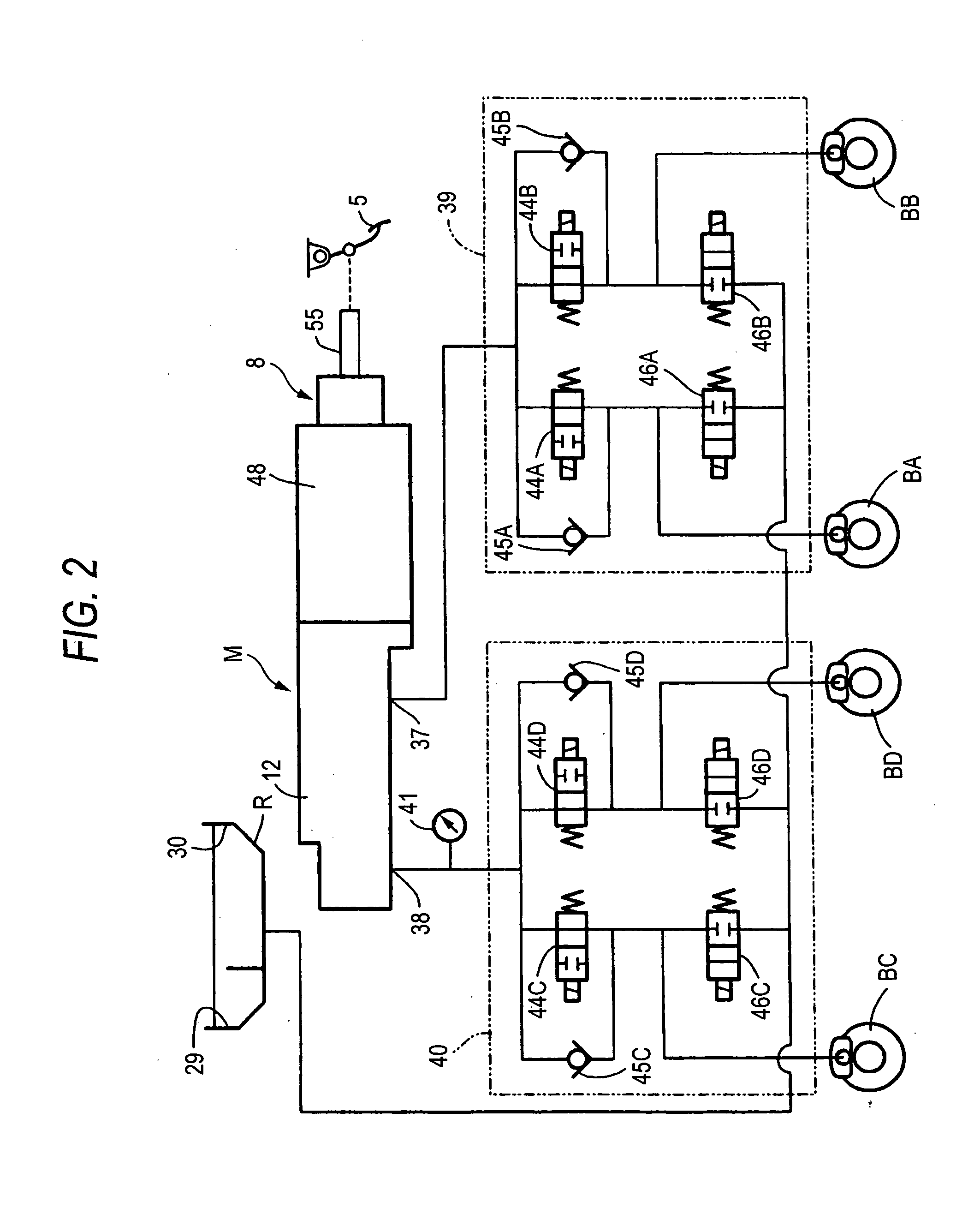
[0035]FIGS. 1 and 2 are such as to shown a first embodiment of the invention, of which FIG. 1 is a brake hydraulic pressure system diagram showing an overall configuration of a vehicle brake apparatus, and FIG. 2 is a hydraulic pressure circuit diagram showing the configuration of a hydraulic pressure modulator.

[0036]Firstly, in FIG. 1, a brake system of a four-wheel vehicle includes a tandem type master cylinder M, a pressure regulator valve unit 7 adapted to regulate the hydraulic pressure of a hydraulic pressure generating source 6 in response to an input of brake application effort from a brake pedal 5 functioning as a brake operation member for application to the master cylinder M, and a stroke simulator 8 adapted to simulate an operation stroke of the brake pedal 5.

[0037]In the master cylinder M, a rear master piston 10, of which back side faces a boosted hydraulic pressure chamber 9 and which is biased rearwards by a spring, and a front master piston 11, which is disposed in ...

Example

[0105]FIGS. 3 and 4 show a second embodiment of the invention, in which like reference numerals will be imparted to constituent components thereof which correspond to their counterparts in the first embodiment that has been described above, so that the detailed description thereof will be omitted here.

[0106]Firstly, in FIG. 3, a secondary casing 48′, which has a tertiary cylinder bore 47 into which a backup piston 49 of a stroke simulator 8 is slidably fitted, is fluid tightly connected to a rear end of a primary casing 12 of a master cylinder M, and an output port 84 is provided in this secondary casing 48′ so as to communicate with a boosted hydraulic pressure chamber 9.

[0107]In addition, a front output port 38 in the master cylinder M is connected to a wheel brake BC for a left front wheel via a left front wheel hydraulic pressure modulator 85, and a rear output port 37 in the master cylinder M is connected to a wheel brake BA for a right front wheel via a right front wheel hydra...


PUM


Abstract

A pressure regulating valve unit 7 is configured to be electrically driven according to a detection value of a detection unit 74 adapted to detect an amount of brake application effort made by a brake operation member 5 so as to switch states of the vehicle brake apparatus between a state where a boosted hydraulic pressure chamber 9 is made to communicate with a hydraulic pressure generating source 6 while a communication between the boosted hydraulic pressure chamber 9 and a reservoir R is interrupted, a state where the communication between the boosted pressure chamber 9 and the hydraulic pressure generating source 6 is interrupted while the boosted pressure chamber 9 is made to communicate with the reservoir R, and a state where the boosted hydraulic pressure chamber 9 is disconnected from both the hydraulic pressure generating source 6 and the reservoir R.

Description

BACKGROUND OF THE INVENTION[0001]1. Field of the Invention[0002]The present invention relates to a vehicle brake apparatus including a master cylinder having a master piston of which back side faces a boosted hydraulic pressure chamber and a casing accommodating the master piston in a slidable manner, a hydraulic pressure generating source, a reservoir, and a pressure regulating valve unit adapted to regulate an output hydraulic pressure of the hydraulic pressure generating source in response to an input of brake application effort from a brake operation member for application to the boosted hydraulic pressure chamber, the master cylinder being connected to wheel brakes.[0003]2. Description of Related Art[0004]A vehicle brake apparatus like one described above is known in, for example, Japanese Patent Unexamined Publication No. JP-A-2002-264795.[0005]In the conventional brake system described above, however, the pressure regulating valve unit is configured to mechanically operate in...

Claims


Application Information

Patent Timeline
IPC IPC(8): B60T13/68
CPCB60T7/042B60T8/441B60T8/446B60T13/143B60T13/145B60T13/148B60T13/165B60T13/686
Inventor SUZUKI, JIROSAKAI, KOJITAGATA, KAZUHIRO
Owner AUTOLIV NISSIN BRAKE SYST JAPAN CO LTD
Why Eureka
Try Eureka