Electrical control device

Active Publication Date: 2008-10-02
LEVITON MFG
View PDF24 Cites 59 Cited by
  • Summary
  • Abstract
  • Description
  • Claims
  • Application Information

AI Technical Summary

Benefits of technology

[0004]One of the benefits of the invention is that if a springboard is formed integral with a support board or a rack, this reduces complexity in assembly and can also reduce manufact

Problems solved by technology

In addition, the use of metallic material for these spring boards can result in unnecessary interference when using an antenna enclosed within a wall mounted electrical device but disposed adjacent to t

Method used


Image

  • Electrical control device
  • Electrical control device
  • Electrical control device

Examples


second embodiment

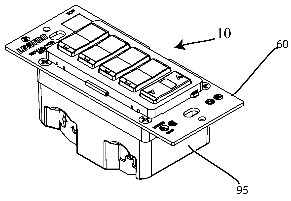
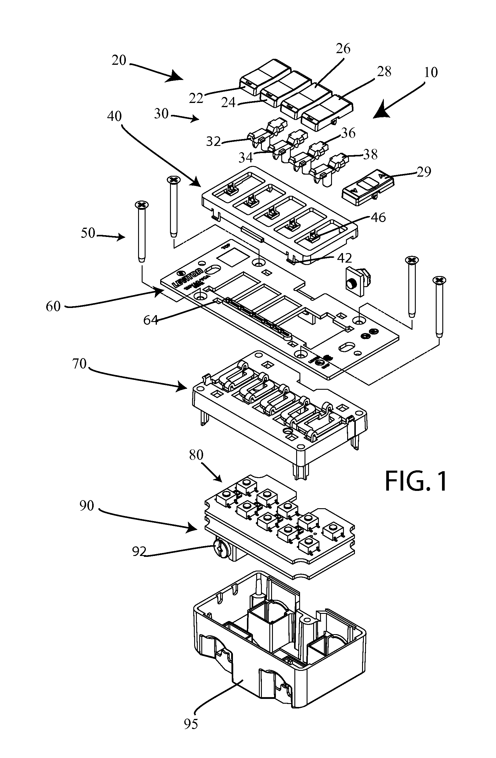
[0043]FIG. 6 discloses a perspective view of the invention. This view shows face plates or frame 210 which can be used to support a plurality of buttons 220 as well as an additional rocker button 229. These buttons can be fit into the frame and an associated strap 230 wherein strap 230 can be secured to a back cover 295 via screws 240. Disposed below strap 230 is a support board 250. Support board 250 is for supporting a plurality of springboards above a plurality of associated switches on a circuit board, such as circuit boards 270 and 290. Circuit board 270 includes plurality of contacts and a plurality of light emitters. Circuit board 290 functions as a power circuit board having an associated contact 292 for receiving power from a power line and then feeds this power into circuit board 270. Once strap 230 is secured to cover 295 via screws 240, support board 250 as well as circuit boards 270 and 290 are disposed in a housing formed by back cover 295 and between strap 230 and cov...

first embodiment

[0054]Once this device is fully assembled, antenna 300 is disposed beneath frame 230, but is disposed outside of a housing formed by strap 230 and cover 295. Similar to the first embodiment, frame 210 can be snapped into strap 230, wherein catch 212 can be snapped into snap holes 232.

[0055]In addition, frame 210 can be easily removed from strap 230 by simply laterally pressing on frame 210 to release catches 212 (See FIG. 6) from strap holes 232. For example, in this case, a user could use a screwdriver to laterally press on frame 210 and use a flat head of the screwdriver to pull underneath frame 210 to pop it out from strap 230. That user could then replace this frame with a different colored frame to provide a substantially easily adaptable display for a user. This device once assembled can be used as a scene controller wherein each of the push buttons 222, 224, 226, and 228 can be used to set for example, dimmer settings on a light or series of lights in a room. Other uses for t...


PUM


Abstract

An electrical device is disclosed for use in a wall box having a series of buttons that can either be rocker buttons or push buttons. These buttons can be supported by springboards formed integral with a support board. The springboards are for biasing the series of buttons. Much of the device is housed within a housing formed at a first end by a body and a second end by a strap coupled to the housing. The strap extends beyond the body, wherein this strap can be used to dissipate heat from the device. Inside of the housing can be at least one circuit board which has switches, which can be used to receive instructions from a plurality of buttons. In one embodiment, a plurality of light pipes are adapted so that they are housed at least partially inside of these buttons. At least one portion of the light pipe can be formed as a shaft and adapted to extend out from this housing and down to a light emitter disposed on the circuit board. In at least one embodiment, this light pipe can also include at least one actuator which is used to contact an associated springboard when a button is acted on. This movement causes the springboard to contact an actuator on a TAC switch which then results in an associated set of instructions being sent to the circuit board.

Description

BACKGROUND OF THE INVENTION[0001]The invention relates to a compact and efficiently designed electrical control device having buttons for allowing a user to control different electrical devices. To support these buttons, there is a spring board to bias these buttons in a particular direction.[0002]In the past, spring boards that have been used to support either rocker mechanisms or push buttons have been made from a metallic material which may result in these spring boards being formed as separate from a support board supporting these spring boards. In addition, the use of metallic material for these spring boards can result in unnecessary interference when using an antenna enclosed within a wall mounted electrical device but disposed adjacent to these spring boards. Furthermore, previous designs of electrical devices have been cumbersome because different elements such as light pipes and buttons were not coupled together in a space saving manner.SUMMARY OF THE INVENTION[0003]One em...

Claims


Application Information

Patent Timeline
IPC IPC(8): H01H9/16H01H1/00
CPCH01H9/168H01H9/52H01H13/705H01H13/83H01H2219/062H01H2221/018H01H2235/022H01H2237/004H01H2239/004
Inventor PATEL, PARIMALLOMBARDI, ALFRED J.ESTANISLAO, DANILO F.
Owner LEVITON MFG
Why Eureka
Try Eureka