

Flushing device and flushing method for a vacuum toilet
a vacuum toilet and flushing device technology, applied in the direction of sewage draining, transportation and packaging, aircraft crew accommodation, etc., can solve the problems of further amplification, noise emission, and noise emission, and achieve the effect of reducing noise emission during the flushing process and ensuring the cleaning effect of the toilet bowl
- Summary
- Abstract
- Description
- Claims
- Application Information
AI Technical Summary
Benefits of technology
Problems solved by technology
Method used
Image

Examples
Embodiment Construction
[0045]Below, a preferred exemplary embodiment of the invention is described with reference to the enclosed drawing.
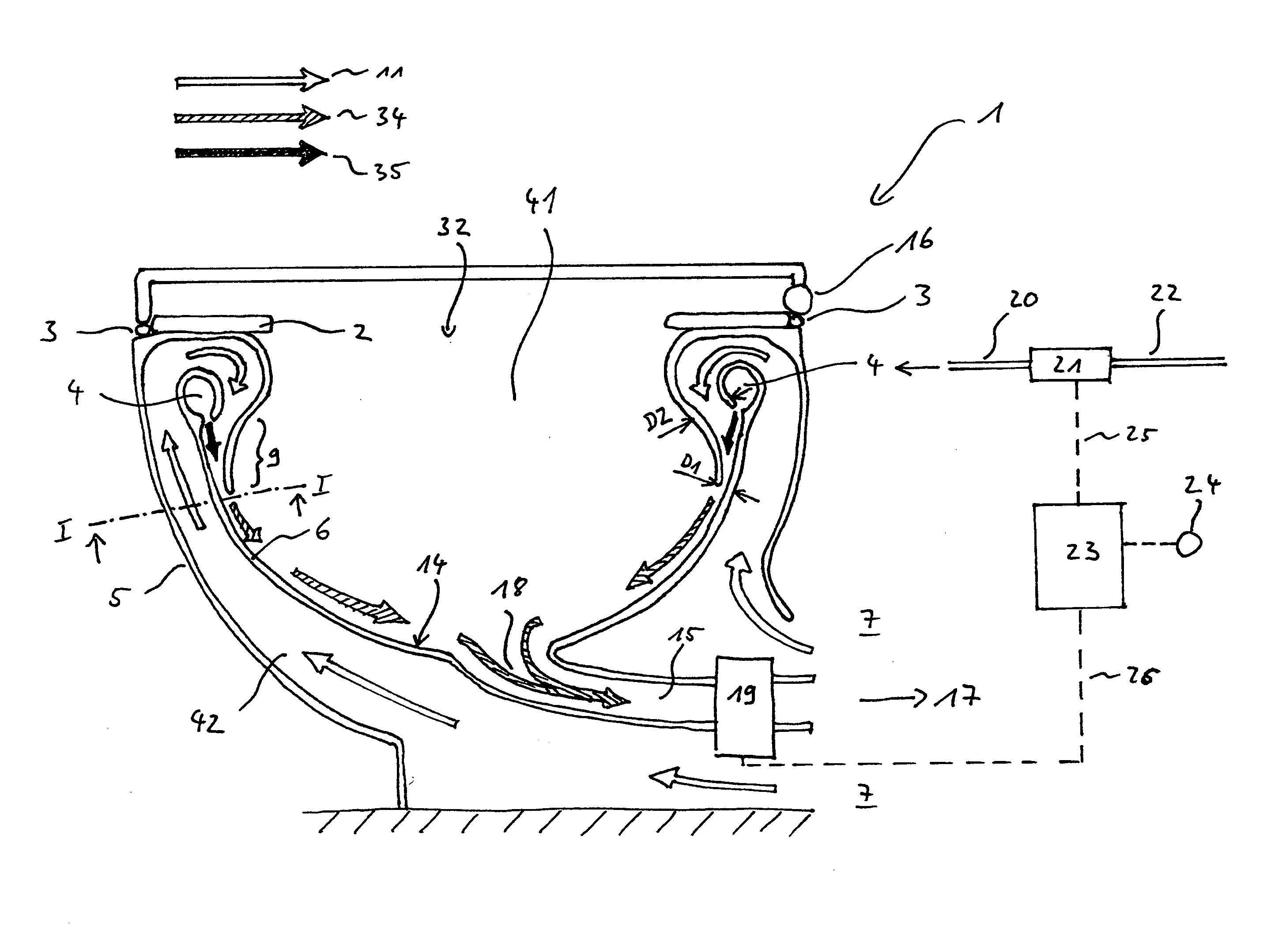
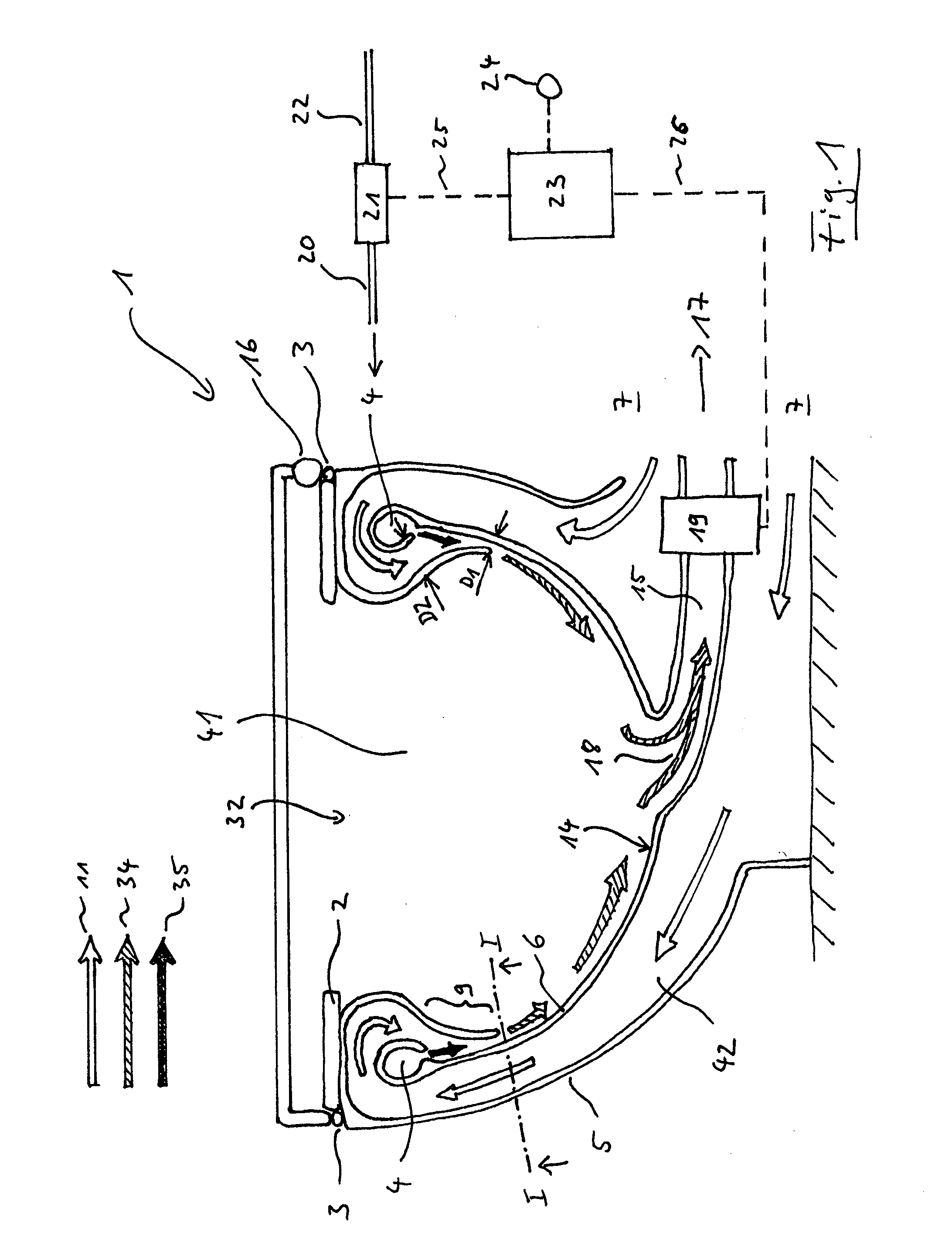
[0046]FIG. 1 shows a section view of an exemplary embodiment of the vacuum toilet 1 according to the invention. This section view not only illustrates the individual components of the vacuum toilet 1, but also the flow patterns of the flushing medium 11, 34, 35.
[0047]It should be noted that the term “liquid flushing medium”35 can, for example, refer to water, and also to any other liquid that is suitable for flushing. Likewise, the term “gaseous flushing medium”11 can, for example, refer to air, and also to any other gas or gas mixture that is suitable for flushing. The use of the terms “water” or “air” in the context of the description is thus merely exemplary; it should not in any way be interpreted as having a limiting effect; the terms in this document are used only to describe the subject of the invention in a way that is easier to understand.
[0048]A completely gas...
PUM
 Abstract
Description
Claims
Application Information