Fault-tolerant permanent magnet machine with reconfigurable flux paths in stator back iron

a permanent magnet machine and flux path technology, applied in the direction of magnetic circuits characterised by magnetic materials, magnetic circuit shapes/forms/construction, nuclear engineering, etc., can solve the problems of reducing the ability to operate the engine properly, pm machines can experience faults, existing fault tolerance pm generators suffer, etc., to achieve the effect of reducing internal hea

Active Publication Date: 2008-10-02
GENERAL ELECTRIC CO
View PDF47 Cites 21 Cited by
  • Summary
  • Abstract
  • Description
  • Claims
  • Application Information

AI Technical Summary

Benefits of technology

[0011]The fault condition mechanism disposed within the stator back iron is reconfigurable to automatically reduce internal heat associated with the PM machine during a fault condition.

Problems solved by technology

When operating an aircraft engine at relatively low power levels, e.g., while idly descending from altitude, extracting this additional electrical power from the engine mechanical power may reduce the ability to operate the engine properly.
However, aviation applications require fault tolerance, and as discussed below, PM machines can experience faults under certain circumstances and existing techniques for fault tolerant PM generators suffer from drawbacks, such as increased size and weight.
When PM machines have been used in such applications, fault-tolerance has been achieved by paying a penalty in the form of oversized machines and / or converter designs, or using a higher number of phases which complicates the control process and adds to the overall system weight and cost.
Consequently, should an electrical device having a PM experience a fault, it may not be possible to expediently stop the device because of the persistent magnetic field of the PM causing the device to keep operating.
Such faults may be in the form of fault currents produced due to defects in the stator windings or mechanical faults arising from defective or worn-out mechanical components disposed within the device.
Hence, the inability to control the PM during the above mentioned or other related faults may damage the PM machine and / or devices coupled thereto.
Further, fault-tolerant systems currently used in PM machines substantially increase the size and weight of these devices limiting the scope of applications in which such PM machines can be employed.
Moreover, such fault tolerant systems require cumbersome designs of complicated control systems, substantially increasing the cost of the PM machine.

Method used


Image

  • Fault-tolerant permanent magnet machine with reconfigurable flux paths in stator back iron
  • Fault-tolerant permanent magnet machine with reconfigurable flux paths in stator back iron
  • Fault-tolerant permanent magnet machine with reconfigurable flux paths in stator back iron

Examples


Embodiment Construction

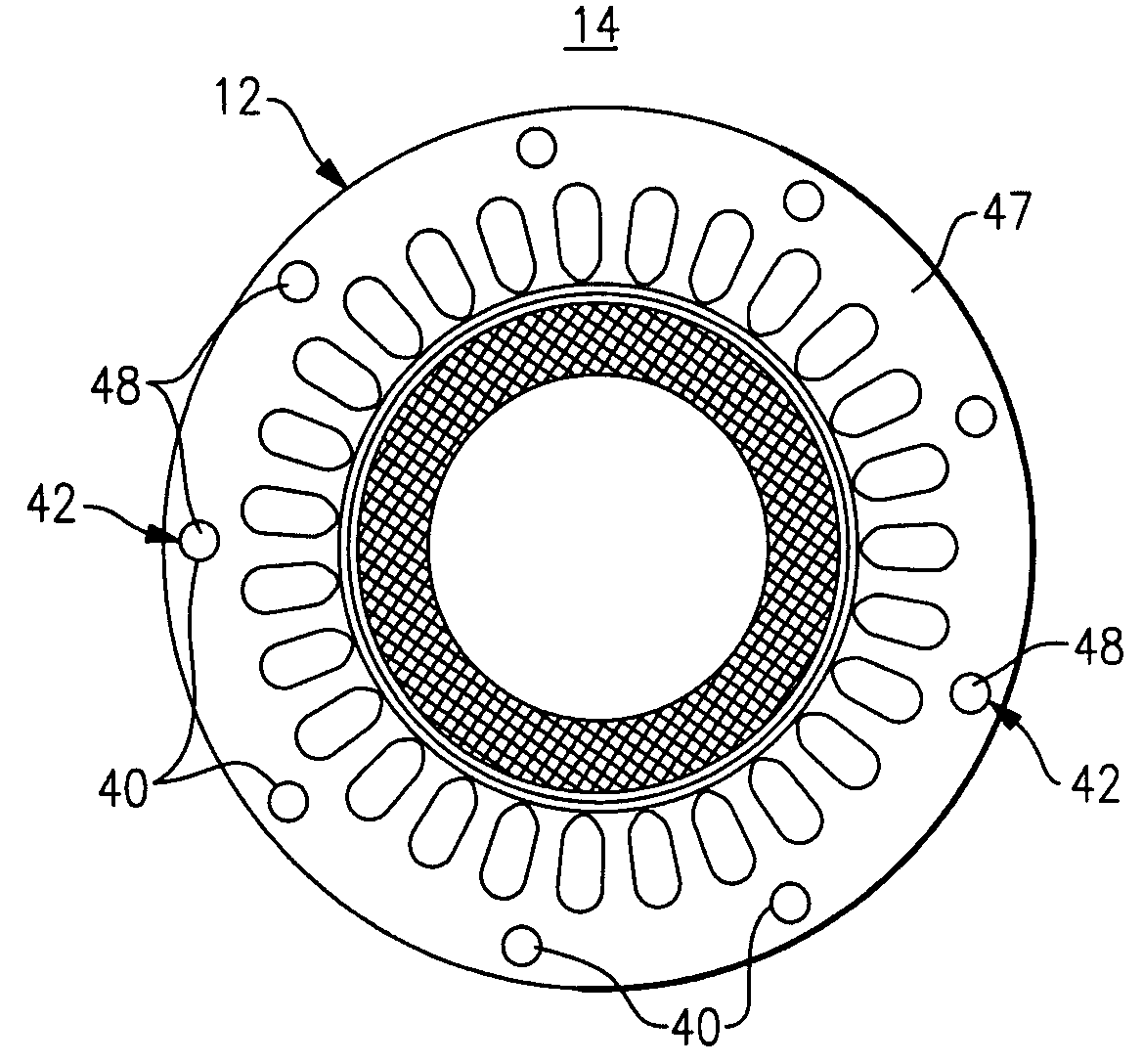
[0024]Conventional PM synchronous electric machines employ permanent magnets as the magnetic poles of a rotor, around which a stator is disposed. The stator has a plurality of teeth that face the rotor. Alternatively, the machine may be designed so that the rotor surrounds the stator. For high-speed operation, a retaining sleeve is usually wrapped around the magnets as needed to keep the magnets in place. The retaining sleeve may be shrink fit upon the magnets to ensure a non-slip fit. Usually the retaining sleeve is made of one whole metallic piece for structural integrity. When the coils formed on the stator are energized, a magnetic flux is induced by the current through the coils, creating electromagnetic forces between the stator and the rotor. These electromagnetic forces contain tangential and / or circumferential forces that cause the rotor to rotate.

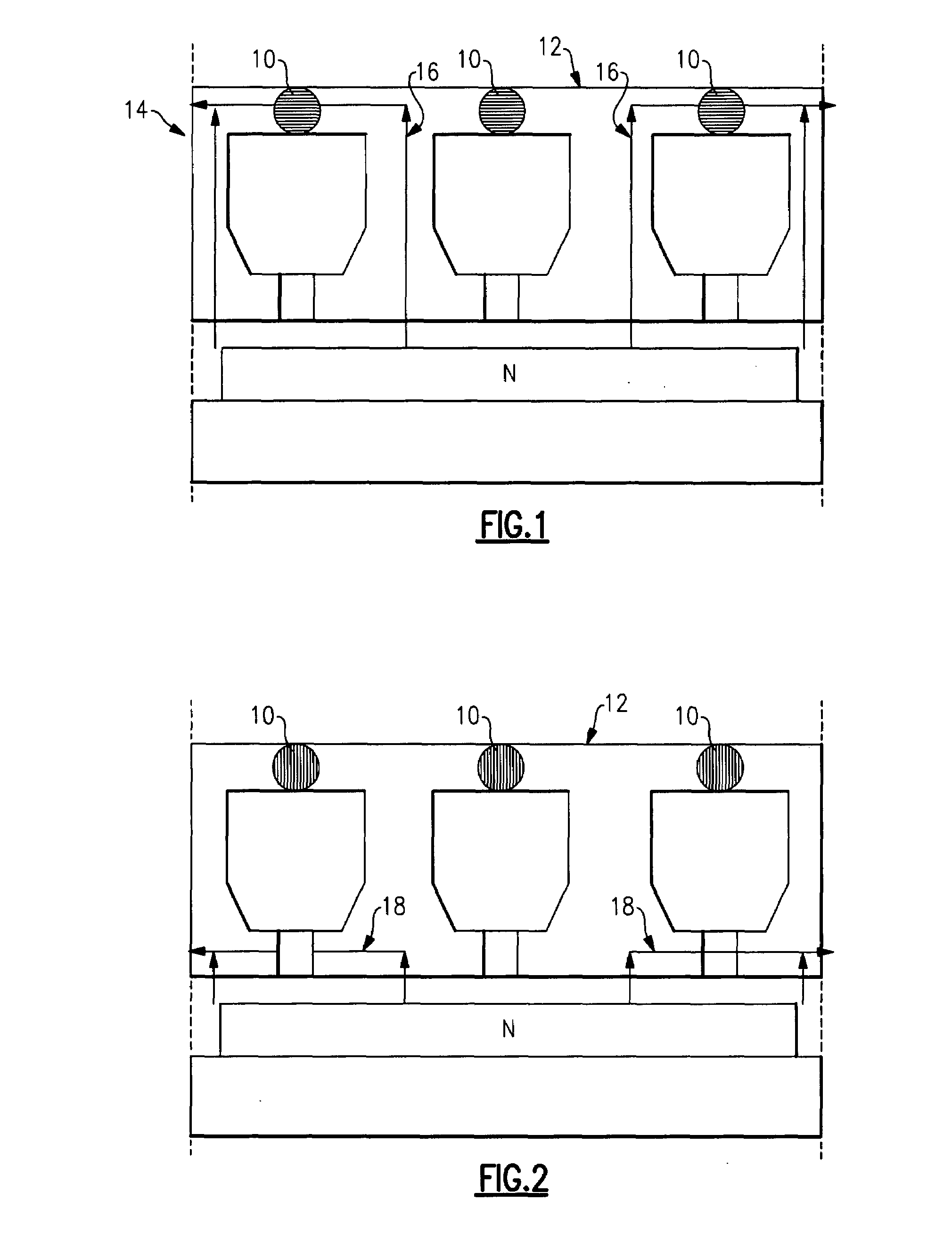
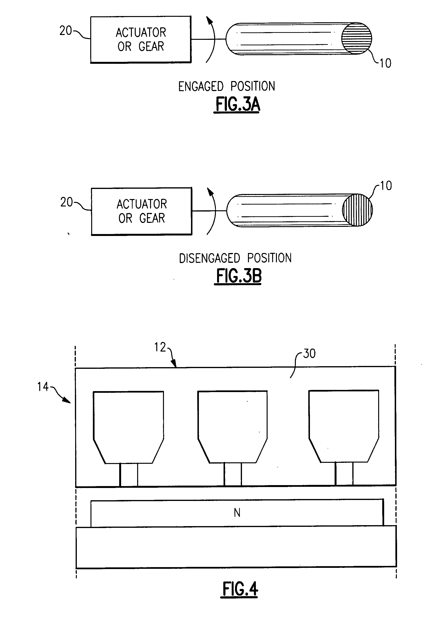
[0025]In order to achieve inherent fault-tolerance in these PM machines, there has to be complete electromagnetic, thermal, and ...


PUM


Abstract

A permanent magnet (PM) machine has a fault condition mechanism disposed within a back iron of the stator portion, the mechanism operational to automatically reduce fault currents associated with the PM machine during a fault condition. The fault condition mechanism disposed within the stator back iron is reconfigurable to automatically reduce internal heat associated with the PM machine during a fault condition. A method of reconfiguring the PM machine upon detecting a fault condition includes the steps of 1) selecting the reconfigurable fault condition mechanism from a) a plurality of magnetically anisotropic rotatable cylinders, b) a plurality of ferrofluid-filled cavities, and c) a dual-phase material selectively embedded within the stator core; and 2) reconfiguring the fault condition mechanism to automatically reduce fault currents or internal heat associated with the PM machine upon detection of a fault condition.

Description

BACKGROUND[0001]The present invention is directed to permanent magnet machines, and more particularly to a method of making a permanent magnet machine more fault-tolerant.[0002]Many new aircraft systems are designed to accommodate electrical loads that are greater than those on current aircraft systems. The electrical system specifications of commercial airliner designs currently being developed may demand up to twice the electrical power of current commercial airliners. This increased electrical power demand must be derived from mechanical power extracted from the engines that power the aircraft. When operating an aircraft engine at relatively low power levels, e.g., while idly descending from altitude, extracting this additional electrical power from the engine mechanical power may reduce the ability to operate the engine properly.[0003]Traditionally, electrical power is extracted from the high-pressure (HP) engine spool in a gas turbine engine. The relatively high operating speed...

Claims


Application Information

Patent Timeline
Patent Type & Authority Applications(United States)
IPC IPC(8): H02H7/08H02K21/12H02K44/00
CPCH02K1/02H02K1/16H02K7/12H02K21/12H02K2213/09H02K2213/06
Inventor SHAH, MANOJ RAMPRASADKERN, JOHN MICHAELEL-RAFAIE, AYMAN MOHAMED FAWZI
Owner GENERAL ELECTRIC CO
Why Eureka
Try Eureka