Biological signal detector

a biological signal and detector technology, applied in the field of signal detectors, can solve the problems of inconvenient driver, difficult to obtain biological signals with stability, difficult to accurately measure pulse waves and electrocardiographic waves, etc., and achieve the effect of easy installation in a small area, easy matching, and simple manufactur

Inactive Publication Date: 2008-10-02
DENSO CORP
View PDF1 Cites 29 Cited by
  • Summary
  • Abstract
  • Description
  • Claims
  • Application Information

AI Technical Summary

Benefits of technology

[0019]In such a case, the electrode device and the pulse wave sensor can be installed in a small area more easily than when they are separately installed. In addition, the electrode device and the pulse wave sensor can be installed in a less curvy portion of the steering wheel such as the spoke part or the like. Therefore, the electrode device and pulse wave sensor can be more easily matched to the shape of the steering wheel, thereby making manufacture thereof simpler.

Problems solved by technology

When a pulse wave sensor is mounted in a vehicle as mentioned above, the pulse wave sensor may be separate from the steering wheel, requiring the driver to put on a measuring device, which is inconvenient for the driver.
However, some areas of the palm have characteristics that make it difficult to measure pulse waves and electrocardiographic waves accurately.
Even when an electrode device and a pulse wave sensor are located adjacent to each other in the steering wheel, there is a possibility that either the electrode device or the sensor touches, for example, a thick layer of the palm skin, making it difficult to obtain biological signals with stability.

Method used


Image

  • Biological signal detector
  • Biological signal detector
  • Biological signal detector

Examples


Embodiment Construction

[0029]Next, exemplary embodiments of the present invention will be described in detail with reference to the accompanying drawings.

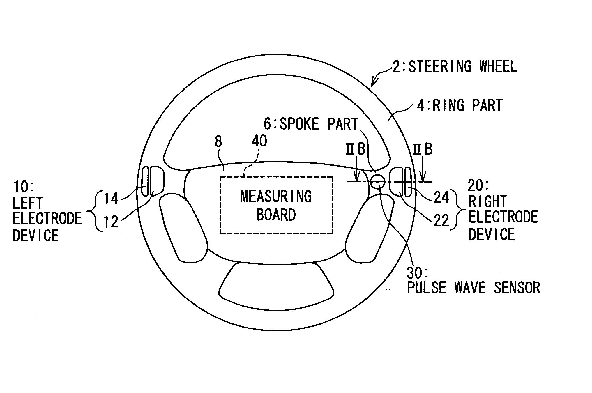
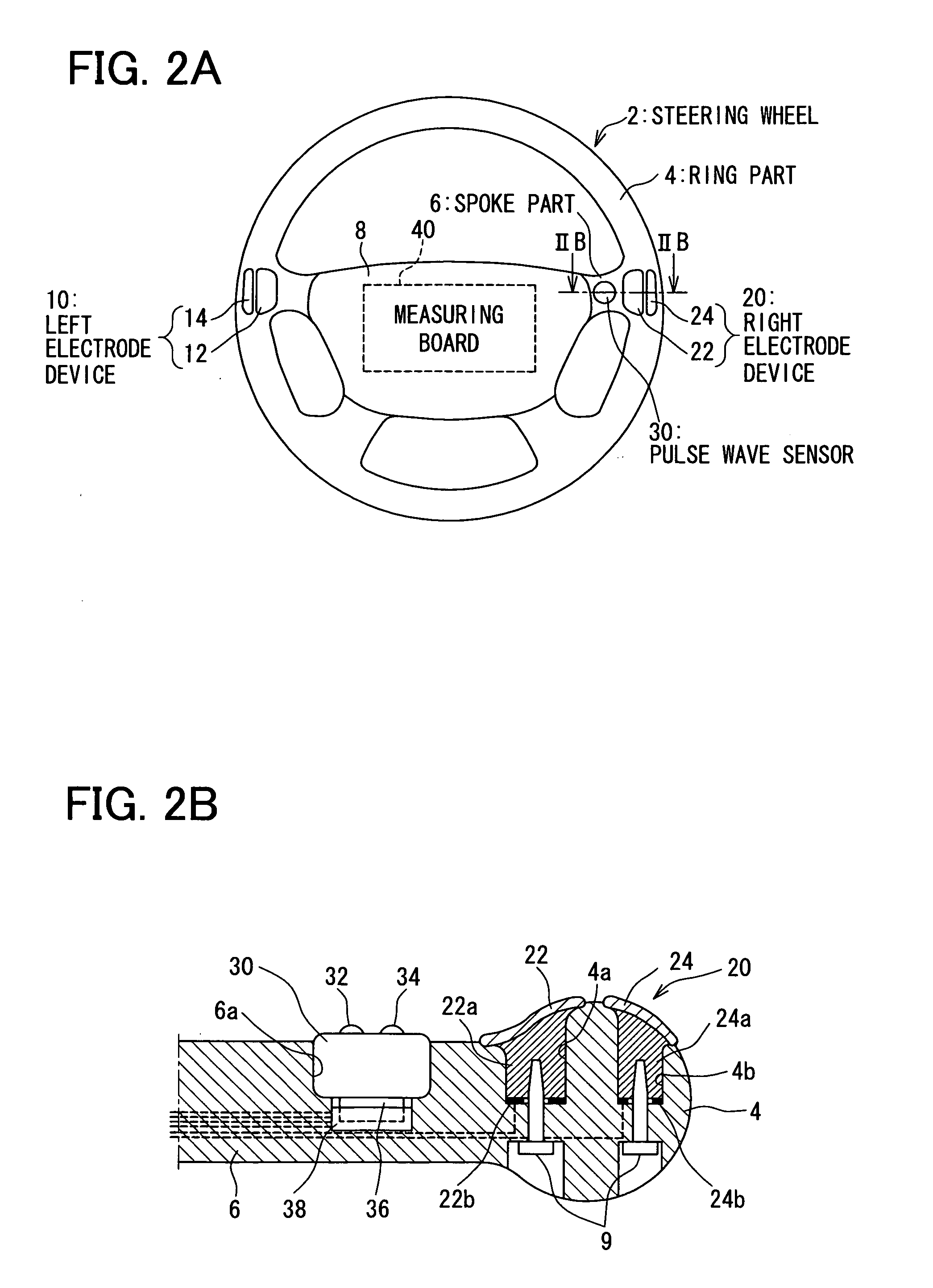
[0030]As shown in FIG. 1, the biological signal detector according to the present embodiment includes a pair of electrode devices including left electrode device 10 and right electrode device 20 for obtaining electrocardiographic signals from a vehicle driver and a pulse wave sensor 30 for obtaining pulse wave signals from the vehicle driver.

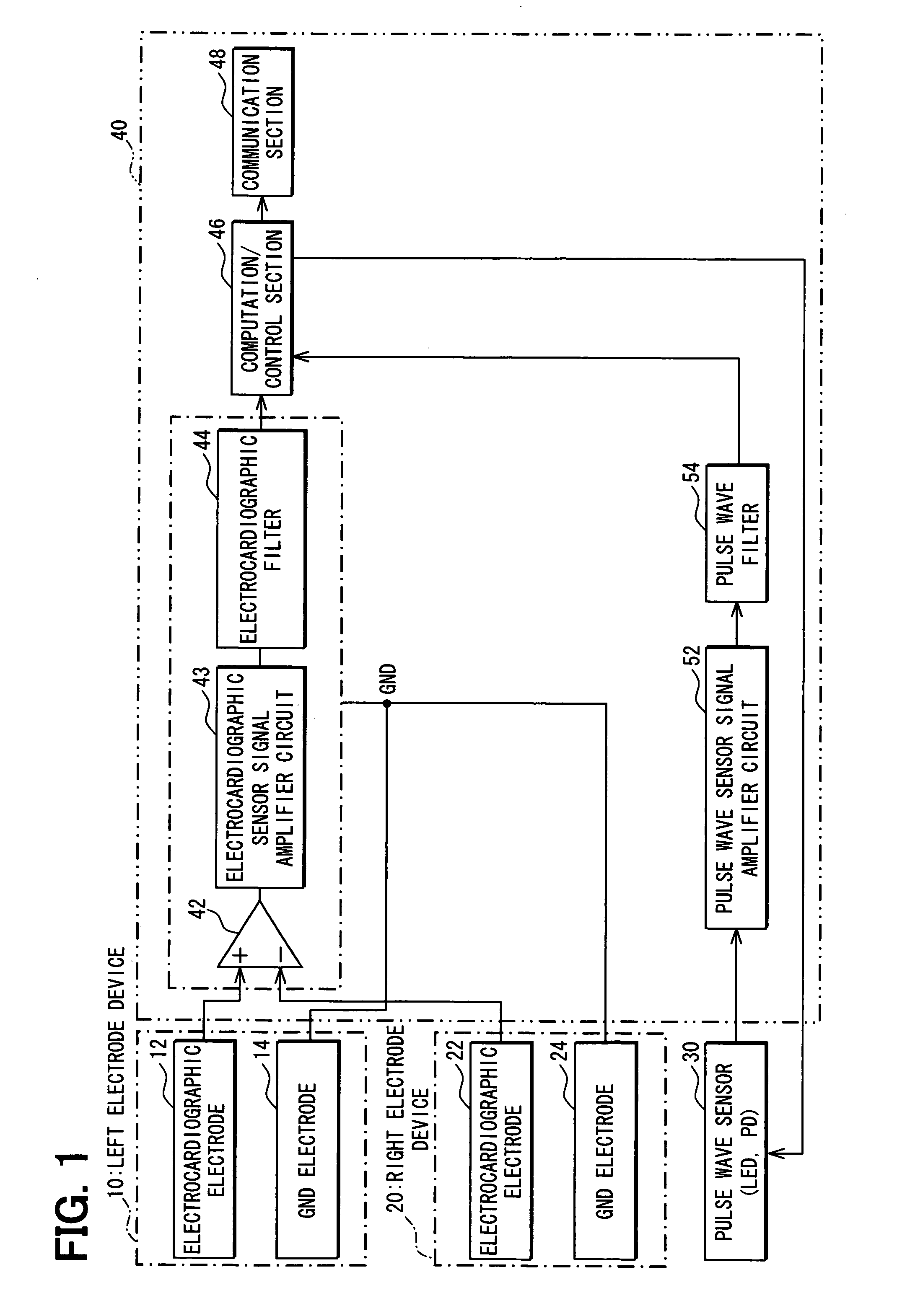
[0031]The left electrode devices 10 and right electrode devices 20 include an electrocardiographic electrode 12, an electrocardiographic electrode 22, a ground or reference (GND) electrode 14, and a GND electrode 24. The electrocardiographic electrodes 12 and 22 are connected respectively with the non-inverting input terminal (+) and inverting input terminal (−) of a differential amplifier circuit 42.

[0032]The differential amplifier circuit 42 outputs a signal that corresponds to a potential difference between signal...


PUM


Abstract

A signal detector detects biological signal associated with a driver using electrode devices and a pulse wave sensor built into a steering wheel. A pulse wave sensor is built into a spoke part of the steering wheel and electrode devices are built into a ring part joined with the left and right spoke parts. The electrode devices and the pulse wave sensor are built into the surface of the steering wheel through insertion into recesses in the steering wheel. The left and right electrode devices and the pulse wave sensor contact thumb bases of the palms of the driver.

Description

CROSS REFERENCE TO RELATED APPLICATIONS[0001]The present invention is based on and claims priority to Japanese Patent Application No. JP 2007-079877 filed on Mar. 26, 2007, and is related to the application entitled “BIOSIGNAL MEASURING EQUIPMENT” reference no. 111276-US based on Japanese Patent Application No. JP 2007-079878 filed on Mar. 26, 2007, the entire contents of all of which are incorporated herein by reference.BACKGROUND OF THE INVENTION[0002]1. Field of the Invention[0003]The present invention relates to a signal detector and more specifically, to a signal detector that obtains a biological signal associated with a driver of a vehicle using an electrode and other components provided on the steering wheel of the vehicle.[0004]2. Description of the Related Art[0005]Measuring instruments provided on the ring or spoke part of the steering wheel of a vehicle for measuring an electrocardiographic signal of a driver are known. Particularly, a pair of left and right electrode de...

Claims


Application Information

Patent Timeline
Patent Type & Authority Applications(United States)
IPC IPC(8): G08B23/00
CPCA61B5/02427A61B5/04085A61B5/18A61B5/6826A61B5/6838A61B2560/0462A61B2560/0468B60K28/06G08B21/04A61B5/282
Inventor YANAI, KENICHIIMURA, SHINGONANBA, SHINJI
Owner DENSO CORP
Why Eureka
Try Eureka