Lamp unit of vehicle headlamp

a headlamp and headlamp technology, applied in the manufacture of electric discharge tubes/lamps, electrode systems, lighting and heating apparatuses, etc., can solve problems such as light distribution unevenness, and achieve the effect of suppressing the occurrence of light distribution unevenness

Inactive Publication Date: 2008-10-02
KOITO MFG CO LTD
View PDF6 Cites 16 Cited by
  • Summary
  • Abstract
  • Description
  • Claims
  • Application Information

AI Technical Summary

Benefits of technology

[0011]One or more embodiments of the invention to provide a lamp unit of a vehicle headlamp capable of suppressing occurrence of light distribution unevenness irrespective of whether a light-emitting element is configured to have a plurality of light-emitting chips arranged so as to be adjacent to each other in a vehicle width direction when a projector-type lamp unit that uses the light-emitting element as a light source is adopted as the lamp unit of a vehicle headlamp.

Problems solved by technology

Because of this, there is a problem in that the gap may be projected as a longitudinally striped dark portion, and thereby light distribution unevenness may be caused in a light distribution pattern.

Method used


Image

  • Lamp unit of vehicle headlamp
  • Lamp unit of vehicle headlamp
  • Lamp unit of vehicle headlamp

Examples


Embodiment Construction

[0032]Hereinafter, embodiments of the invention will be described with reference to the accompanying drawings.

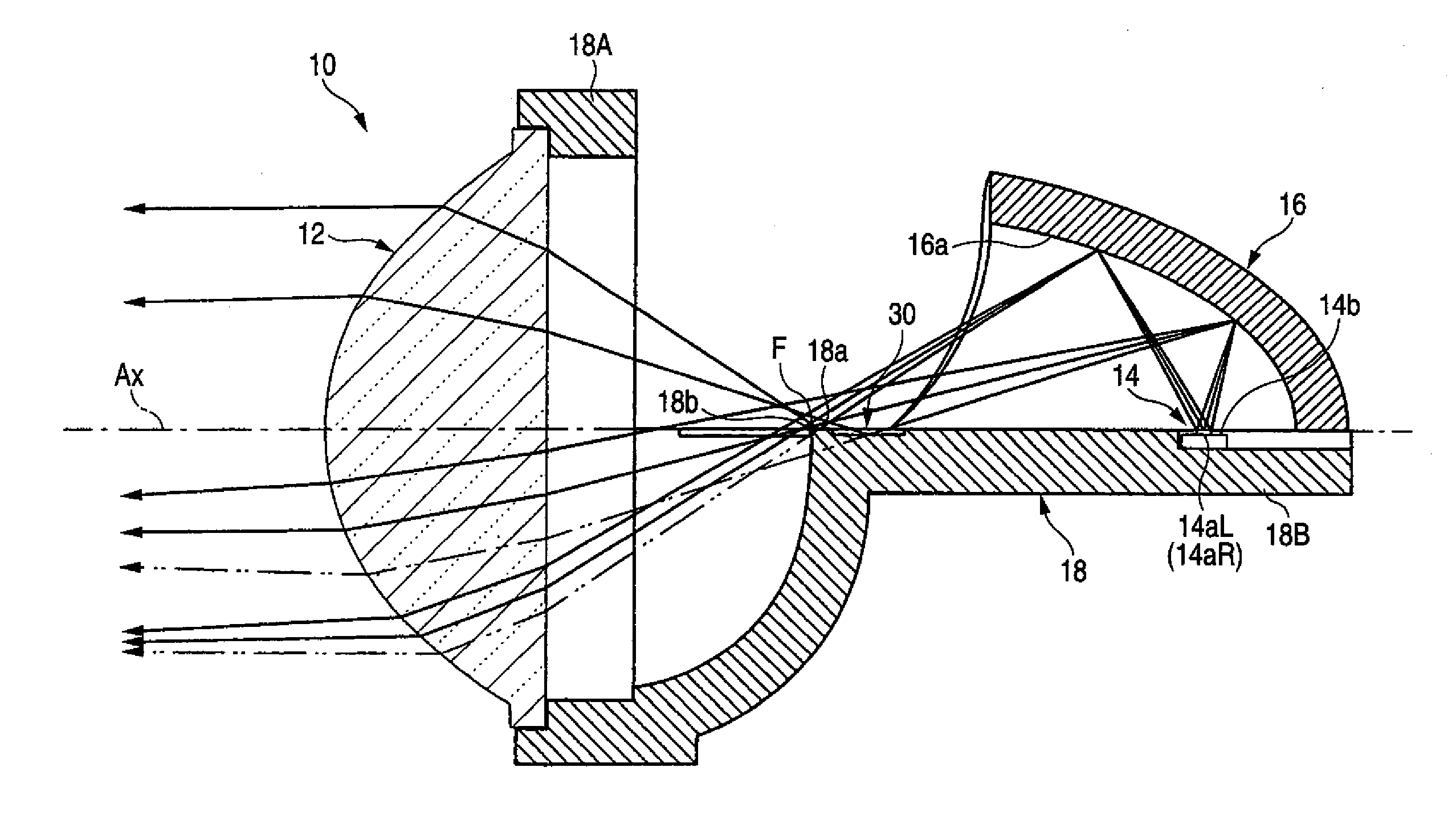
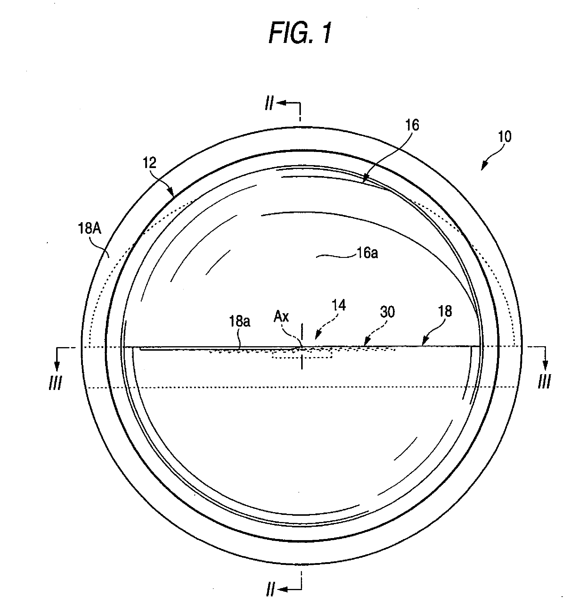
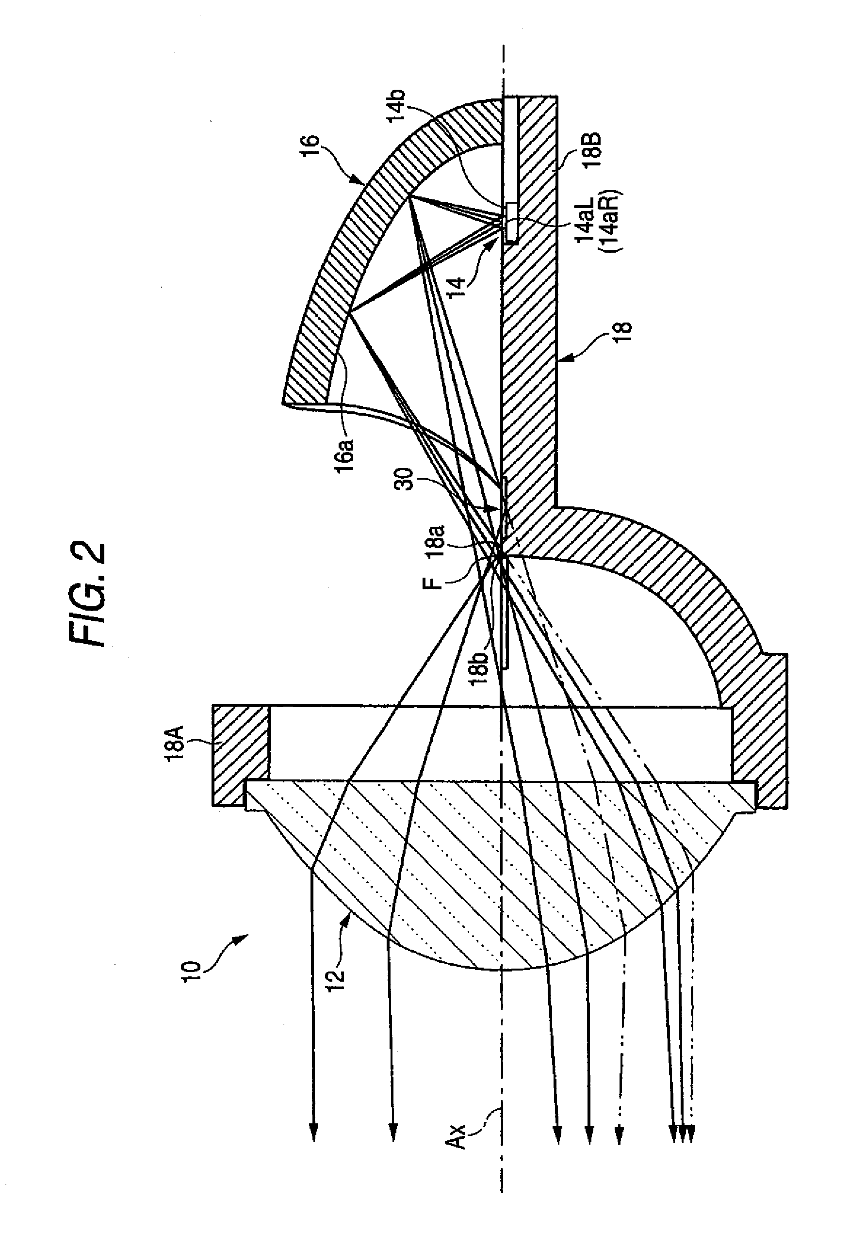
[0033]FIG. 1 is a front view showing a lamp unit 10 according to one embodiment of the invention. Further, FIG. 2 is a sectional view taken along the line II-II of FIG. 1, and FIG. 2 is a sectional view taken along the line III-III of FIG. 1.

[0034]As shown in these drawings, lamp unit 10 includes a projection lens 12 arranged on an optical axis Ax extending in the longitudinal direction of a vehicle, a light-emitting element 14 arranged behind a rear focal point F of the projection lens 12, a reflector 16 arranged so as to cover the light-emitting element 14 from above, and deflects the light from the light-emitting element 14 forward toward the optical axis Ax, and a mirror member 18 arranged between the reflector 16 and the projection lens 12, which reflects a portion of the reflected light from the reflector 16 upward.

[0035]The lamp unit 10 is adapted to be used in a stat...


PUM


Abstract

A lamp unit of a vehicle lamp includes a projection lens arranged on an optical axis extending in the longitudinal direction of a vehicle, a light-emitting element arranged so as to face upward behind a rear focal point of the projection lens and in the vicinity of the optical axis, and a reflector arranged so as to cover the light-emitting element from above and to reflect the light from the light-emitting element forward toward the optical axis. The light-emitting element has a plurality of light-emitting chips arranged so as to be adjacent to each other in a vehicle width direction. A mirror member is provided between the reflector and the projection lens. The mirror member includes an upward reflecting surface that upward reflects a portion of the reflected light from the reflector. A diffusing and reflecting portion that diffuses and reflects the reflected light from the reflector is formed in the upward reflecting surface so as to bridge over the optical axis in the vehicle width direction.

Description

[0001]This application claims foreign priority from Japanese Patent Application No. 2007-079029 filed on Mar. 26, 2007, the entire contents of which are hereby incorporated by reference.BACKGROUND OF THE INVENTION[0002]1. Field of the Invention[0003]The present invention relates to a lamp unit of a vehicle headlamp, and particularly, relates to a projector-type lamp unit that uses a light-emitting element as a light source.[0004]2. Related Art[0005]In recent years, even in vehicle headlamps, lamp units that use a light-emitting element, such as a light-emitting diode, as a light source have been adopted.[0006]For example, Patent Document 1 discloses a so-called projector-type lamp unit including a projection lens arranged on an optical axis extending in the longitudinal direction of a vehicle, a light-emitting element arranged so as to face upward behind a rear focal point of the projection lens and in the vicinity of the optical axis, and a reflector arranged so as to cover the lig...

Claims


Application Information

Patent Timeline
Patent Type & Authority Applications(United States)
IPC IPC(8): B60Q1/00H01J9/00
CPCF21S48/1154F21S48/1159F21S48/1388F21Y2101/02F21Y2115/10F21S41/255F21S41/321F21S41/337F21S41/43F21S41/365F21S41/148B60Q1/04
Inventor NAKADA, YUSUKETSUKAMOTO, MICHIO
Owner KOITO MFG CO LTD
Why Eureka
Try Eureka