Supercharge Your Innovation With Domain-Expert AI Agents!

Method and system for rub detection in a steam turbine

a technology for steam turbines and rub detection, which is applied in the direction of instruments, heat measurement, engine starters, etc., can solve the problems of reducing the efficiency of the turbine, causing the turbine blades to rub against the stationary casing, and damage to the turbine components

Inactive Publication Date: 2008-10-02
GENERAL ELECTRIC CO
View PDF4 Cites 14 Cited by
  • Summary
  • Abstract
  • Description
  • Claims
  • Application Information

AI Technical Summary

Benefits of technology

[0005]A method is disclosed for detecting rubbing between components in a steam turbine, the method includes: sensing a temperature at a plurality of locations on a casing of the steam turbine; comparing the sensed temperatures of the plurality of locations; detecting the rubbing between the components if one of the plurality of locations has a higher sensed temperature than the sensed t...

Problems solved by technology

A slight deformity in the turbine casing, rotor shaft, inner casing or other component can cause the turbine blades to rub against a stationary casing of the turbine.
A rub between a turbine bucket and a stationary component in a steam turbine can damage the turbine components.
The increased clearances, change the flow paths through the turbine and thereby reduce the efficiency of the turbine.
Severe rubbing may cause turbine buckets to fail, break off and damage downstream blades.
Rubbing in a steam turbine is not easily detected.
However, vibration in a turbine is not necessarily indicative of rubbing and vibration sensors have difficulty in determining a rotational position of the rubbing.

Method used


Image

  • Method and system for rub detection in a steam turbine
  • Method and system for rub detection in a steam turbine
  • Method and system for rub detection in a steam turbine

Examples


Embodiment Construction

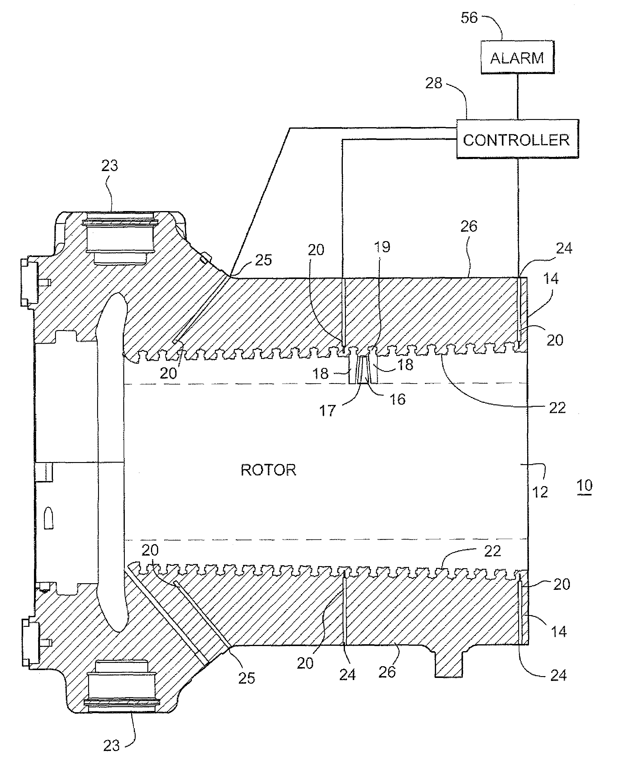
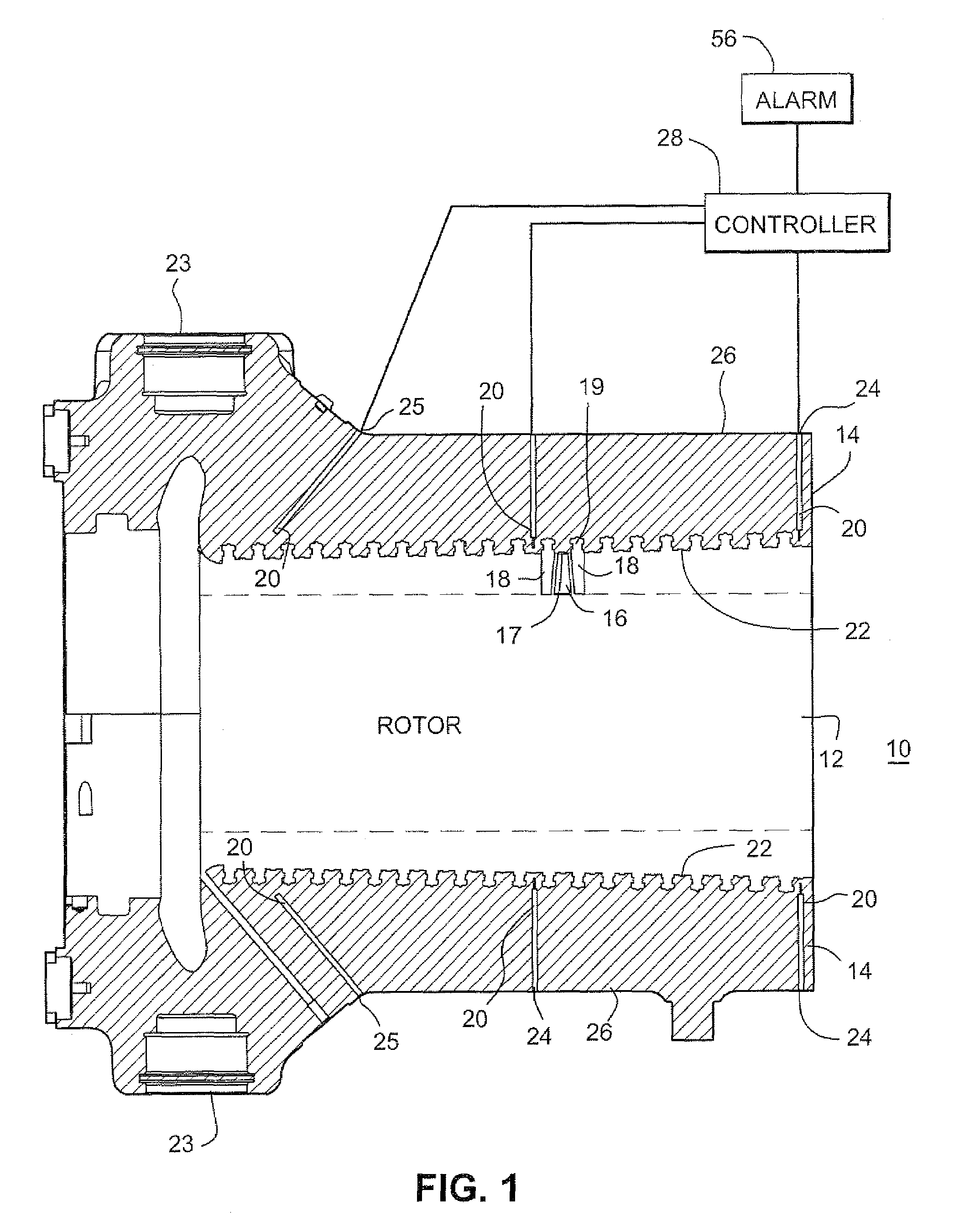
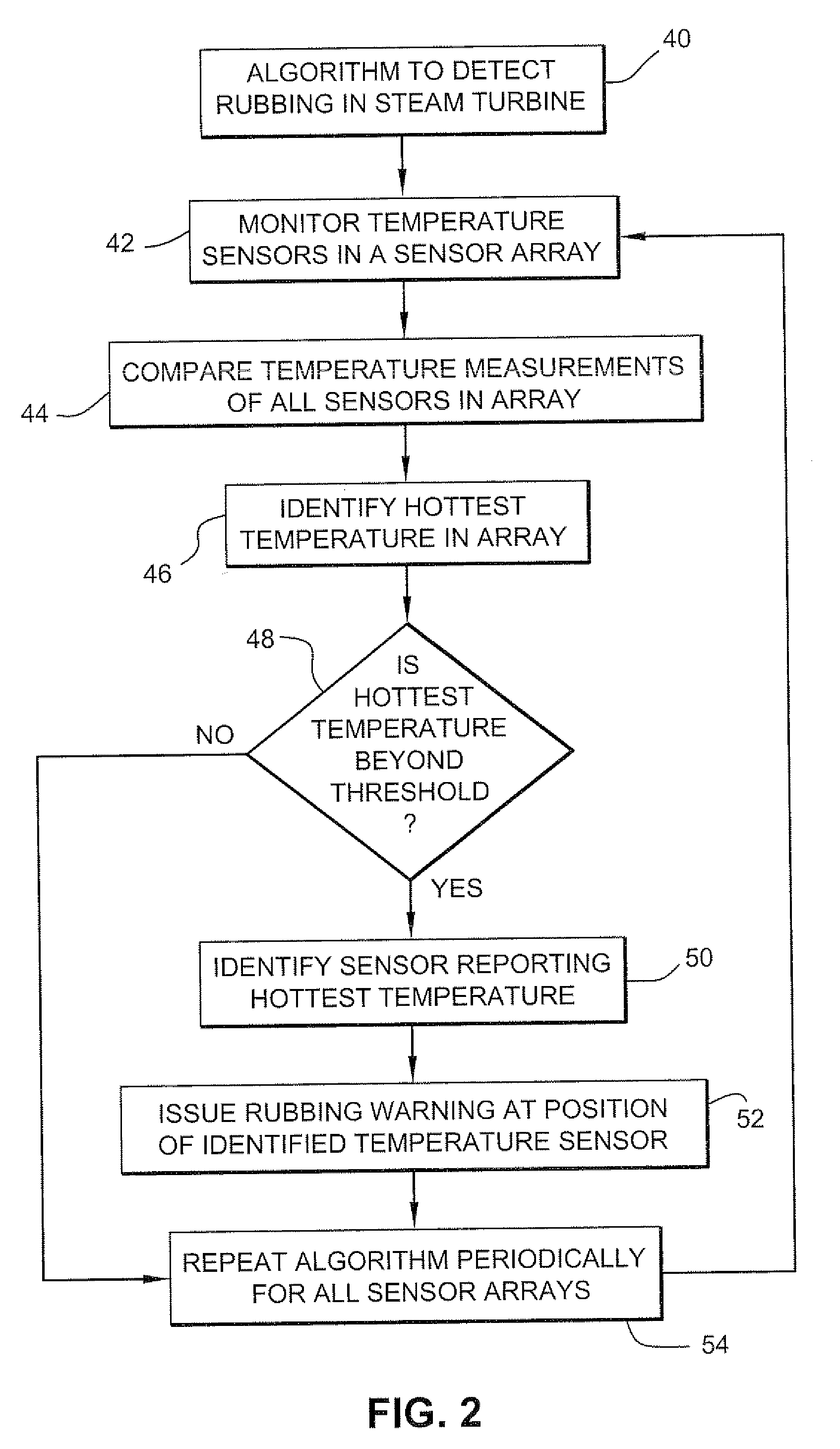
[0010]A novel system and method has been developed to detect rubbing in a steam turbine using temperature sensors on the turbine casing. The friction of rubbing creates heat at the rubbing location. The heating is localized in the metallic casing. Temperature sensors, e.g., thermocouples, embedded in the casing report the temperature increase in the casing due to the rubbing. The sensor reporting a high temperature is determined by comparing the temperature signal reports from an array of thermocouples. A rub is detected when the temperature report from one sensor in the array is sufficiently above the temperature reports from other sensors in the array. The location of the rub is determined to be proximate to the temperature sensor that reported the high temperature.

[0011]FIG. 1 is a side view showing in cross-section a steam turbine 10 having a rotor 12 and a turbine casing 14. The rotor includes rows of turbine rotor buckets 16 (turbine blades) that are each arranged between rows...


PUM


Abstract

A method for detecting rubbing between components in a steam turbine, the method includes: sensing a temperature at a plurality of locations on a casing of the steam turbine; comparing the sensed temperatures of the plurality of locations; detecting the rubbing between the components if one of the plurality of locations has a higher sensed temperature than the sensed temperature at the other plurality of locations, and reporting the rub as being at a location near the one of the plurality of locations having the higher sensed temperature.

Description

BACKGROUND OF THE INVENTION[0001]The present invention relates to instruments for monitoring steam turbines. In particular, the invention relates to detecting rubbing between rotating and stationary components in a steam turbine.[0002]Steam turbines include a rotor with rows of turbine blades (buckets) that rotate between rows of stator blades (nozzles). The tips of the turbine buckets are adjacent an inside surface of the casing for the turbine. During normal operation, the turbine buckets do not rub against the casing. A slight deformity in the turbine casing, rotor shaft, inner casing or other component can cause the turbine blades to rub against a stationary casing of the turbine. The rub is typically at one rotational position, such as when the turbine tip passes through a top position on the casing.[0003]A rub between a turbine bucket and a stationary component in a steam turbine can damage the turbine components. The clearances between the turbine buckets and stator casing ma...

Claims


Application Information

Patent Timeline
IPC IPC(8): F01D21/12
CPCF01D21/12G01K1/026G01K13/04G01N19/02F05D2220/31F05D2270/112F05D2270/3032
Inventor COOPER, GREGORY EDWARD
Owner GENERAL ELECTRIC CO
Features
  • R&D
  • Intellectual Property
  • Life Sciences
  • Materials
  • Tech Scout
  • Unparalleled Data Quality
  • Higher Quality Content
  • 60% Fewer Hallucinations
Learn More