Scroll fluid machine

a fluid machine and scroll technology, applied in machines/engines, couplings, liquid fuel engines, etc., can solve the problems of increasing manufacturing costs, increasing clearance, and producing vibration and noise, so as to prevent the occurrence of torsion of the first scroll relative to the second scroll

Inactive Publication Date: 2008-10-02
ANEST IWATA CORP
View PDF5 Cites 8 Cited by
  • Summary
  • Abstract
  • Description
  • Claims
  • Application Information

AI Technical Summary

Benefits of technology

[0037]According to the invention of claim 6, two groups of arcuate plate springs each consisting of four arcuate plate springs are used to connect the first scroll to the second scroll by fixing an end of an arcuate plate spring to a first support flange of the first scroll and fixing the other end of said arcuate plate spring to a second support flange of the second scroll, in this way, first support flanges provided to the first scroll at equal circumferential spacing and second support flanges provided to the second scroll at equal circumferential spacing are connected by ar

Problems solved by technology

In an Oldham coupling type anti-rotation mechanism, grooves and rectangular protrusions to be received in the grooves are formed as shown in FIG. 9, so abrasion of the grooves and rectangular protrusions tend to occur resulting in increased clearance therebetween, which produces vibration and noise.
In a scroll fluid machine adopting pin crank type anti-rotation mechanism as shown in FIGS. 11a, 11b, usually three pin cranks are provided, and angular contact ball bearings are used to maintain proper clearance between the top faces of the scroll laps and the mating mirror surfaces of the stationary and revolving scrolls, structure becomes complicated resulting in increased manufacturing cost.
Further, the bearings of the pin cranks must be lubricated by lubrication oil or grease, controlling of tempe

Method used


Image

  • Scroll fluid machine
  • Scroll fluid machine
  • Scroll fluid machine

Examples


first embodiment

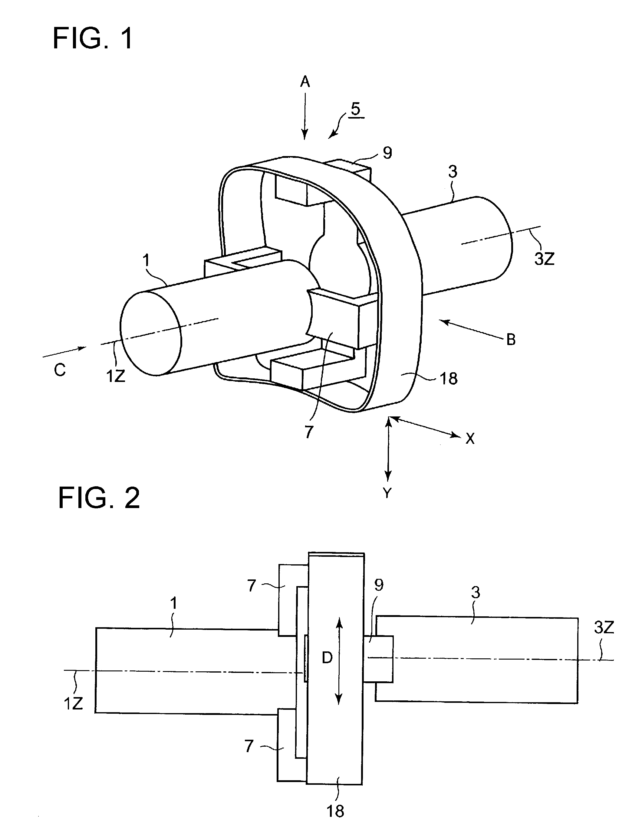
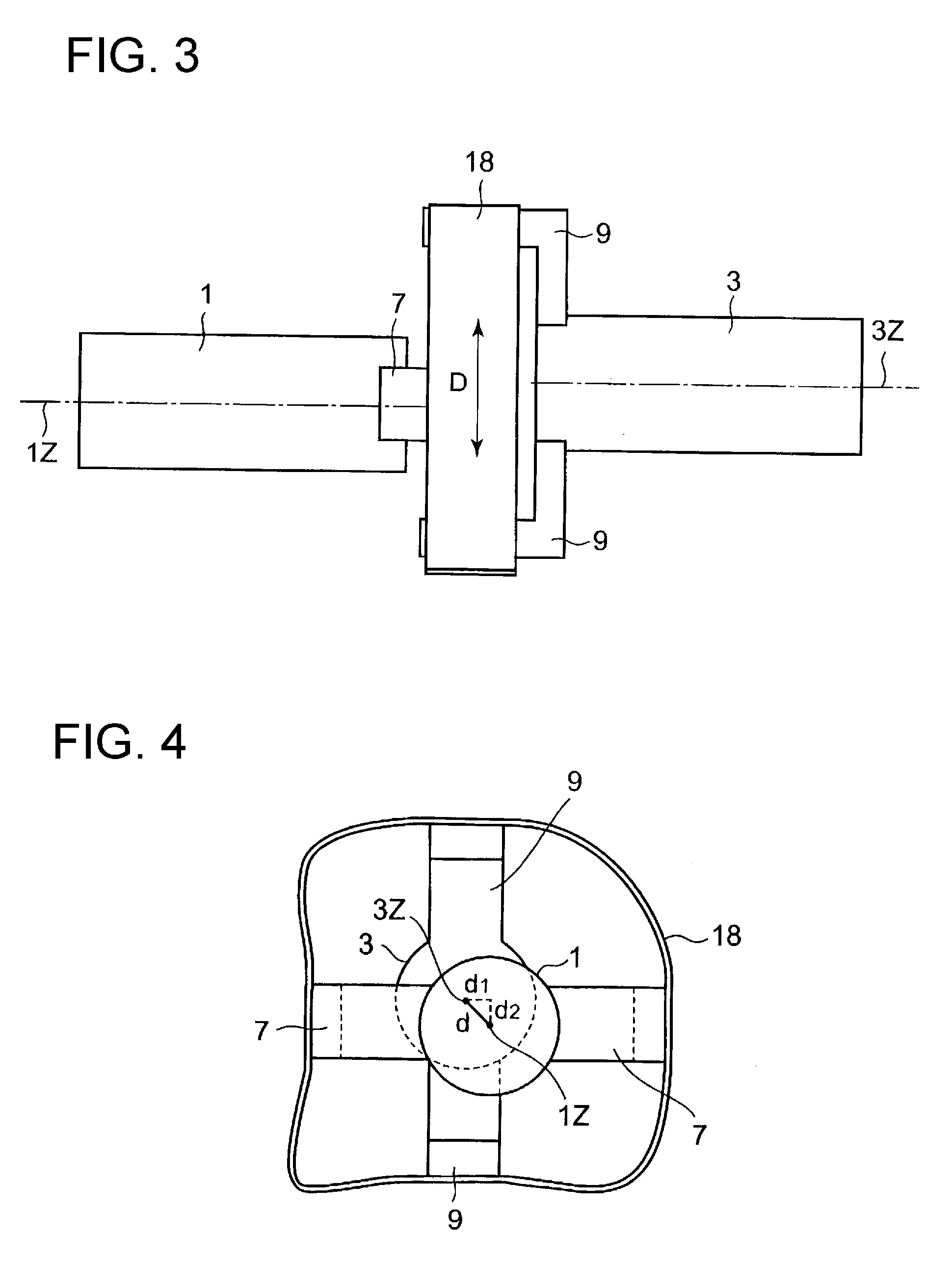
[0060]the scroll fluid machine utilizing the shaft coupling mechanism mentioned above will be explained referring to FIGS. 5 and 6.

[0061]Referring to FIG. 5, a scroll compressor 50 comprises a revolving scroll 52 having a revolving scroll lap 54, a stationary scroll 58 having a stationary scroll lap 58, a scroll casing 60 fixed to the stationary scroll 58 and covering the revolving scroll 52, a motor casing 64 of a motor 62 for driving the revolving scroll 52.

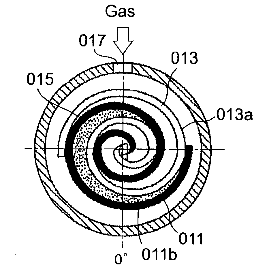
[0062]A discharge port 68 and a discharge opening 70 communicating to the discharge port 68 are provided to the stationary scroll 58 at the center of the stationary scroll plate of which the inside surface is finished to a mirror surface 58a. The stationary scroll lap 56 erects from the mirror surface 58a extending spirally outward from near the periphery of the discharge port 68. A tip seal (not shown) made of self-lubricating material is received in a tip seal groove (not shown) of the stationary scroll lap 56.

[0063]The stati...


PUM


Abstract

The object is to provide a scroll fluid machine in which relative revolving motion is produced between two scrolls engaging with each other without using conventional Oldham coupling or pin crank type mechanism which has sliding parts. The scroll compressor 50 comprises a stationary scroll 58 fixed to a scroll casing 60, a revolving scroll 52, a rotation shaft 86 having an offset portion 100 for revolving the revolving scroll 52, and plate springs 110a 110b that connect the stationary scroll to the revolving scroll in a state surrounding the scroll laps of the scrolls.

Description

TECHNICAL FIELD[0001]The present invention relates to a scroll fluid machine for compressing fluid, specifically relates to a mechanism for revolving the revolving scroll of the scroll fluid machine.BACKGROUND ART[0002]Rotation prevention mechanism for preventing rotation of the revolving scroll and defining the radius of revolution thereof such as a crank mechanism and Oldham coupling has been adopted in scroll fluid machines.[0003]First, the principle of scroll compressor will be explained briefly with reference to FIGS. 8a to 8d. [0004]A scroll compressor consists of a stationary scroll having a spiraling scroll lap 011 and a revolving scroll having a spiral lap 013. Gas ingested from an inlet port 017 is compressed as a revolving scroll revolves and the compressed gas is discharged from a discharge port 025 at the center. A stationary scroll lap 011 is formed on a disk fixed perpendicular to a rotation shaft. The revolving scroll lap 013 and the stationary scroll lap 011 spiral ...

Claims


Application Information

Patent Timeline
IPC IPC(8): F01C1/063
CPCF04C18/0215F04C29/0057F04C18/02
Inventor YANAGISAWA, KEN
Owner ANEST IWATA CORP
Why Eureka
Try Eureka