Nano-scale metal oxyhalide and oxysulfide scintillation materials and methods for making same

a technology of oxysulfide and oxyhalide, which is applied in the direction of tungsten oxide/hydroxide, mercury compounds, oxygen/ozone/oxide/hydroxide, etc., can solve the problems of high limit of time difference measurement, increase production costs and process difficulties, and limit the size of individual pixels

Inactive Publication Date: 2008-10-02
GENERAL ELECTRIC CO
View PDF37 Cites 26 Cited by
  • Summary
  • Abstract
  • Description
  • Claims
  • Application Information

AI Technical Summary

Benefits of technology

[0011]In another embodiment, the present techniques provide a method for making nano-scale particles of an oxyhalide or oxysulfide based scintillation material. The method comprises adding an aqueous base to an aqueous solution comprising one or more metal salts to precipitate a gel containing the one or more metal salts and removing free ions from the gel. The gel is heated and dried to form the nano-scale particles of the oxyhalide or oxysulfide type scintillation material.

Problems solved by technology

The limitations of this time difference measurement are highly dependent on the stopping power, light output, and decay time of the scintillator material.
The dicing process limits the size of the individual pixel, as both production costs and process difficulties increase as the pixel size gets finer.
However these scintillators do not meet the more stringent luminescence requirements for CT systems.
Scintillators based on CsI have a long decay time, leading to afterglow which tends to wash out images.
Furthermore, detectors based on FOS plates do not have the high conversion efficiency needed for accurate imaging.
However, these systems are not very specific to the type of radiation involved, and often may give false alarms.

Method used


Image

  • Nano-scale metal oxyhalide and oxysulfide scintillation materials and methods for making same
  • Nano-scale metal oxyhalide and oxysulfide scintillation materials and methods for making same
  • Nano-scale metal oxyhalide and oxysulfide scintillation materials and methods for making same

Examples


Embodiment Construction

I. Imaging Systems Using Scintillators

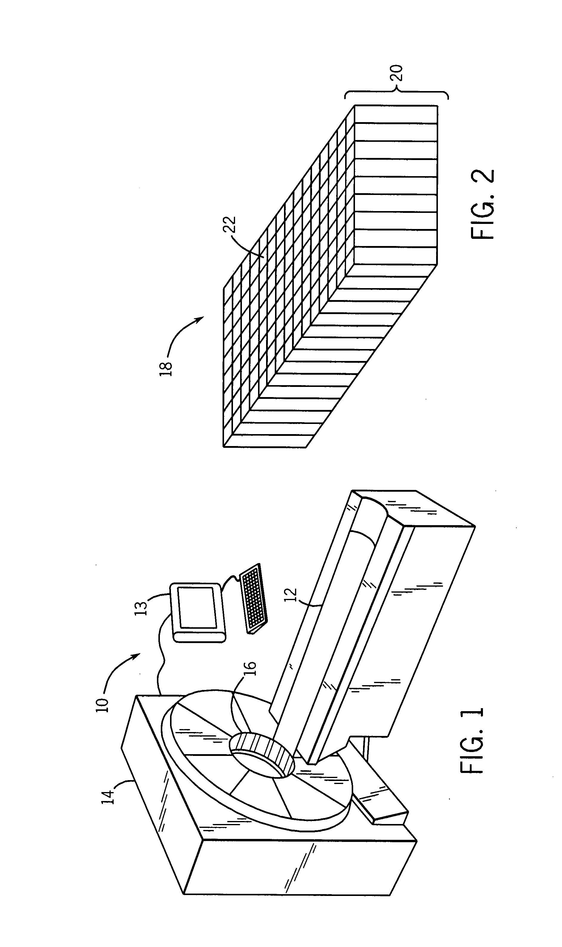
[0032]Embodiments of the present techniques include new scintillation detectors that may be used for the detection of radiation in imaging systems, security systems, and other devices. For example, FIG. 1 illustrates a medical imaging system 10 in accordance with embodiments of the present technique. This system may be, for example, a positron emission tomography (PET) imaging device, a computer-aided tomography (CT) imaging device, a single positron emission computed tomography (SPECT) system, a mammography system, a tomosynthesis system, or a general X-ray based radiography system, among others. The exemplary system has a frame 14, which contains at least a radiation detector, and may include other equipment, such as a pivoting gantry to move X-ray sources and detectors around the patient. In certain embodiments, the patient is placed on a sliding table 12, and moved through an aperture 16 in the frame 14. In such embodiments, as the patient i...


PUM

PropertyMeasurementUnit
sizeaaaaaaaaaa
melting pointaaaaaaaaaa
organicaaaaaaaaaa

Abstract

Crystalline scintillator materials comprising nano-scale particles of metal oxides, metal oxyhalides and metal oxysulfides are provided. The nano-scale particles are less than 100 nm in size. Methods are provided for preparing the particles. In one method, used to form oxyhalides and oxysulfides, metal salts are dissolved in water, and then precipitated out as fine particles using an aqueous base. After the particles are separated from the solution, they are annealed under a flow of a water saturated hydrogen anion gas, such as HCl or H2S, to form the crystalline scintillator particles. The other methods take advantage of the characteristics of microemulsion solutions to control droplet size, and, thus, the particle size of the final nano-particles. For example, in one method, a first micro-emulsion containing metal salts if formed. The first micro-emulsion is mixed with an aqueous base in a second micro-emulsion to form the final nano-scale particles.

Description

BACKGROUND[0001]The present invention relates generally to a scintillation material for making scintillation detectors. More specifically, the invention provides a scintillation material comprising nano-scale particles of either a metal oxyhalide or a metal oxysulfide, and methods for preparing the same.[0002]Scintillators are materials that convert high-energy radiation, such as X-rays and gamma rays, into visible light. Scintillators are widely used in detection and non-invasive imaging technologies, such as imaging systems for medical and screening applications. In such systems, high-energy photons typically pass through the person or object undergoing imaging and, on the other side of the imaging volume, impact a scintillator associated with a light detection apparatus. The scintillator typically generates optical photons in response to the high-energy photon impacts. The optical photons may then be measured and quantified by the light detection apparatus, thereby providing a su...

Claims


Application Information

Patent Timeline
Patent Type & Authority Applications(United States)
IPC IPC(8): C01B13/14C01F17/00C01G11/00C01G41/02C01G9/02C01F17/241C01F17/253C01F17/259
CPCB82Y30/00C01B13/328C01F17/0043C01F17/0056C01F17/0093C01G1/06C01G1/12C01P2002/54C01P2004/64C01F17/294C01F17/253C01F17/259C01F17/241
Inventor CLOTHIER, BRENT ALLENLOUREIRO, SERGIO PAULO MARTINSSRIVASTAVA, ALOKSTOKLOSA, STANLEY JOHNDUCLOS, STEVEN JUDEVENKATARAMANI, VENKAT SUBRAMANIAM
Owner GENERAL ELECTRIC CO
Why Eureka
Try Eureka