Membrane electrode assembly for fuel cell and process for manufacturing the same

a fuel cell and membrane electrode technology, applied in the direction of cell components, sustainable manufacturing/processing, electrolyte stream management, etc., can solve the problem of degrading the electric-power generation performance of conventional fuel cells, and achieve the effect of improving water dischargeability

Inactive Publication Date: 2008-10-02
TOYOTA JIDOSHA KK
View PDF6 Cites 24 Cited by
  • Summary
  • Abstract
  • Description
  • Claims
  • Application Information

AI Technical Summary

Benefits of technology

[0011]The present invention has been developed in view of the aforementioned circumstances. It is therefore an object of the present invention to provide a membrane ...

Problems solved by technology

Moreover, the publication does not at all deal with a technology on catalytic layer, but deals with a technology on gas diffusi...

Method used


Image

  • Membrane electrode assembly for fuel cell and process for manufacturing the same
  • Membrane electrode assembly for fuel cell and process for manufacturing the same
  • Membrane electrode assembly for fuel cell and process for manufacturing the same

Examples


embodiment form no.1

Embodiment Form No. 1

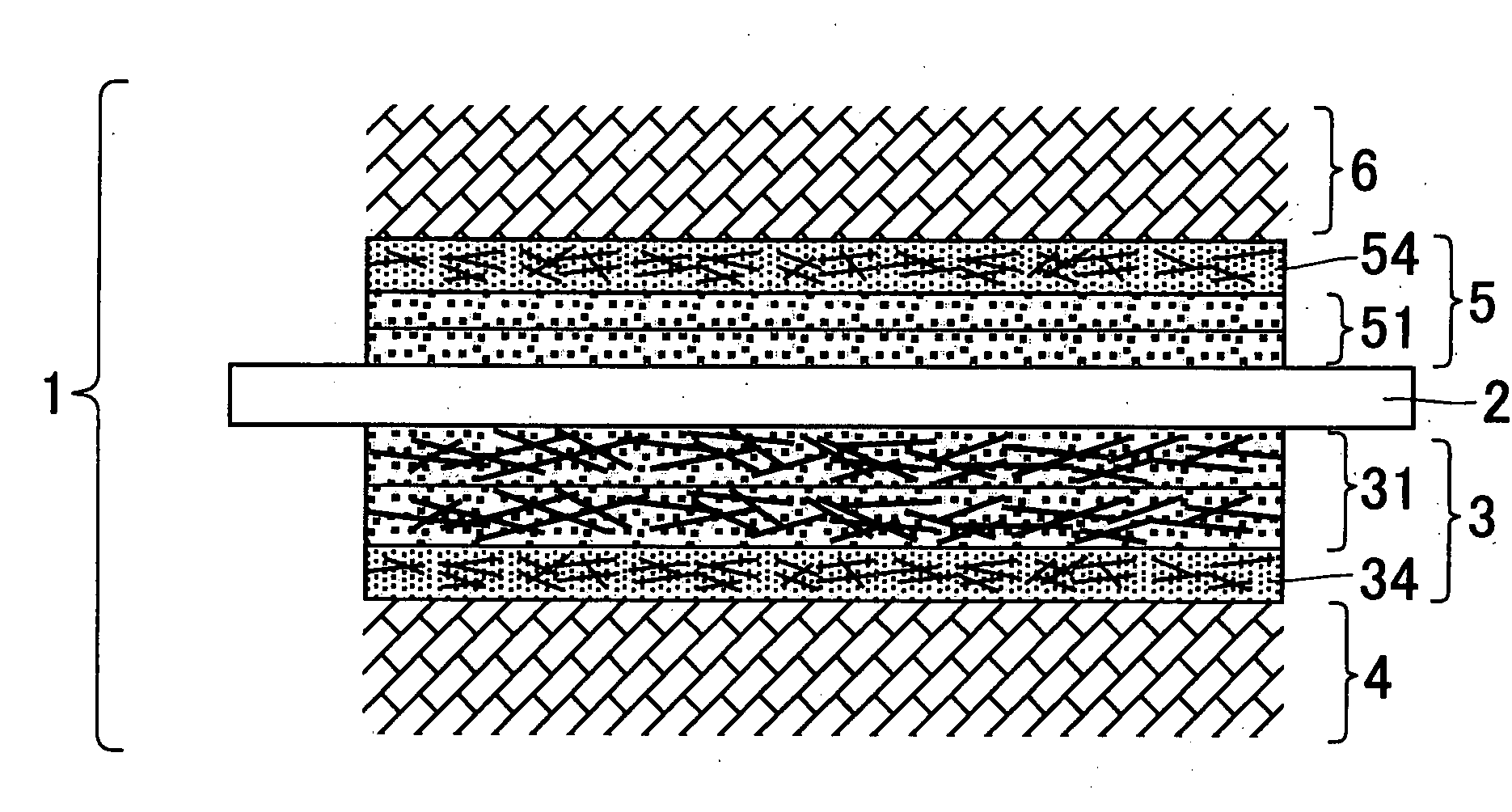
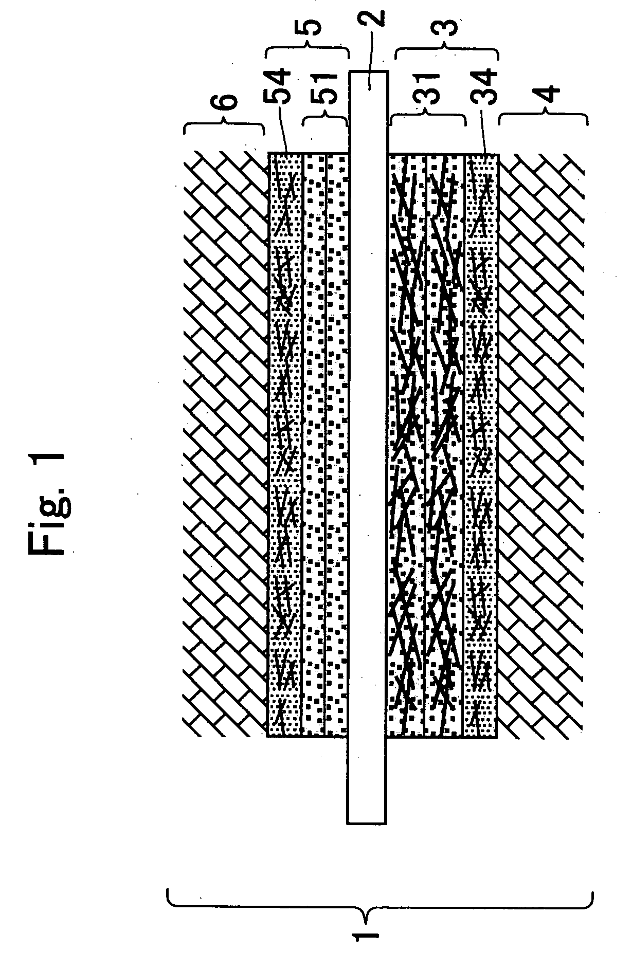
[0056]Embodiment Form No. 1 of the present invention will be hereinafter described with reference to FIG. 1. A membrane electrode assembly (hereinafter referred to as “MEA” wherever appropriate) according to Embodiment Form No. 1 for fuel cell is used in proton-exchange membrane fuel cells. As illustrated in FIG. 1, an MEA 1 comprises a membrane 2, a cathode electrode layer 3, a cathode gas diffusion layer 4, an anode electrode layer 5, and an anode gas diffusion layer 6. The membrane 2 is formed of a polymeric material, which exhibits ionic conductivity, for example, a perfluorosulfonic acid resinous material. The cathode electrode layer 3 is disposed on one of the thickness-wise opposite surfaces of the membrane 2, or on one of the thickness-wise opposite sides of the MEA 1. The cathode gas diffusion layer 4 is disposed on the thickness-wise outer side of the cathode electrode layer 3. The anode electrode layer 5 is disposed on the other one of the thickness-w...

embodiment form no.2

Embodiment Form No. 2

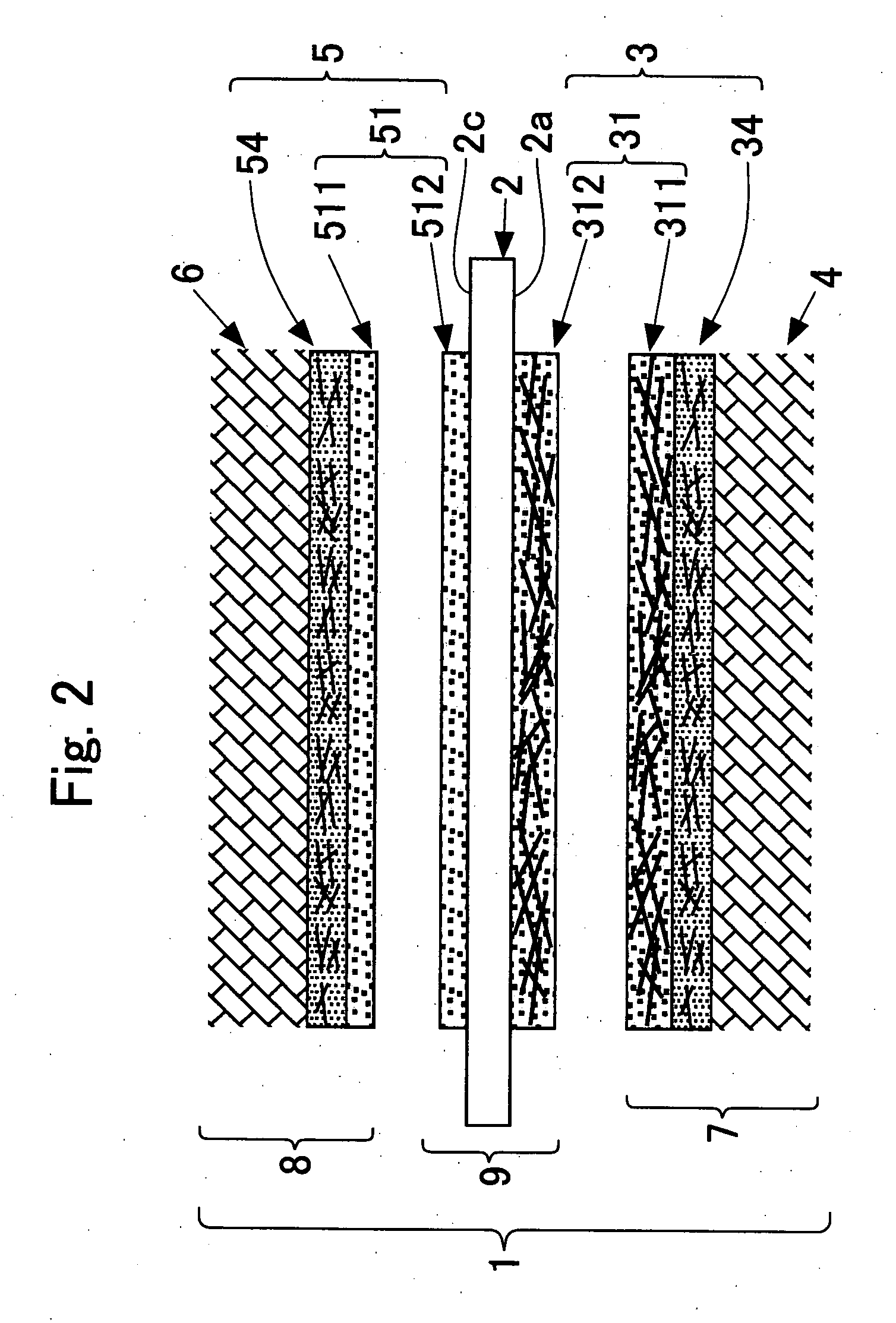
[0067]Embodiment Form No. 2 of the present invention will be hereinafter described with reference to FIG. 2. Basically, Embodiment Form No. 2 comprises the same constituent elements as those of Embodiment Form No. 1, and operates and effects advantages in the same manner as Embodiment No. 1. In accordance with Embodiment Form No. 2, first of all, the following are prepared: longer carbon fibers whose average fibrous length is longer relatively; and shorter carbon fibers whose average fibrous length is shorter relatively than that of the longer carbon fibers. Note herein that the longer carbon fibers exhibit an average fibrous length of from 10 to 50 micrometers, and an average fibrous diameter of from 0.05 to 0.3 micrometers, for instance. Moreover, the shorter carbon fibers exhibit an average fibrous length of from 3 to 9 micrometers, and an average fibrous diameter of from 0.05 to 0.3 micrometers, for instance.

[0068]Secondly, as illustrated in FIG. 2, a first ...

embodiment form no.3

Embodiment Form No. 3

[0074]Embodiment Form No. 3 of the present invention will be hereinafter described with reference to FIG. 3. Basically, Embodiment Form No. 3 comprises the same constituent elements as those of Embodiment Form No. 2, and operates and effects advantages in the same manner as Embodiment Form No. 2. Embodiment Form No. 3 will be hereinafter described while focusing on the constituent elements of Embodiment Form No. 3 that differ from those of Embodiment Form No. 2. In Embodiment Mode No. 3 as well, the first catalytic layer 31 in the cathode electric layer 3 comprises the first inner catalytic layer 312, and the first outer catalytic layer 311. The first inner catalytic layer 312 is disposed nearer to the membrane 2 in the thickness-wise direction of the MEA 1. The first outer catalytic layer 311 is disposed more away from the membrane 2 than the first inner catalytic layer 312 is disposed in the thickness-wise direction of the MEA 1. Moreover, the first catalytic ...


PUM

PropertyMeasurementUnit
Lengthaaaaaaaaaa
Thicknessaaaaaaaaaa
Electrical conductoraaaaaaaaaa

Abstract

A membrane electrode assembly for fuel cell includes a membrane, a cathode electrode layer, a cathode gas diffusion layer, an anode electrode layer, and an anode gas diffusion layer. At least one of the cathode electrode layer and the anode electrode layer includes a catalytic layer, and a water-repellent layer. The catalytic layer contains first electrically-conductive fibers and a catalyst, and is disposed on a side of the membrane in the thickness-wise direction of the membrane electrode assembly. The water-repellent layer contains second electrically-conductive fibers and a water repellent, and is disposed more away from the membrane than the catalytic layer is disposed in the thickness-wise direction of the membrane electrode assembly. The first electrically-conductive fibers exhibit a first fibrous average length. The second electrically-conductive fibers exhibit a second fibrous average length. The first average fibrous length is longer than the second average fibrous length.

Description

[0001]The present invention is based on Japanese Patent Application No. 2007-79,598, filed on Mar. 26, 2007, the entire contents of which are incorporated herein by reference.BACKGROUND OF THE INVENTION[0002]1. Field of the Invention[0003]The present invention relates to a membrane electrode assembly for fuel cell, and a process for manufacturing the same.[0004]2. Description of the Related Art[0005]A conventional membrane electrode assembly comprises a membrane, a cathode electrode layer, a cathode gas diffusion layer, an anode electrode layer, and an anode gas diffusion layer. The membrane exhibits ionic conductivity. The cathode electrode layer is disposed on one of the thickness-wise opposite surfaces of the membrane. The cathode gas diffusion layer is disposed on the thickness-wise outer side of the cathode electrode layer. The anode electrode layer is disposed on the other one of the thickness-wise opposite surfaces of the membrane. The anode gas diffusion layer is disposed on...

Claims


Application Information

Patent Timeline
IPC IPC(8): H01M4/86B32B37/14
CPCB32B37/144B32B2309/02B32B2309/04B32B2309/105B32B2327/18B32B2457/18H01M4/8605H01M4/8642H01M4/8657H01M4/8807H01M4/881H01M4/8817H01M4/8896H01M8/04276H01M8/1004H01M2008/1095Y02E60/521Y02P70/50Y02E60/50
Inventor KURITA, ATSUSHIXIE, GANGYAMADA, CHIAKI
Owner TOYOTA JIDOSHA KK
Why Eureka
Try Eureka