Apparatus and method for lapping slider using floating lapping head

a technology of lapping head and apparatus, applied in the direction of lapping machines, instruments, maintaining head carrier alignment, etc., can solve the problem of limited reaction force and achieve the effect of reducing the variation of lapping

Inactive Publication Date: 2008-10-02
SAE MAGNETICS (HK) LTD
View PDF2 Cites 7 Cited by
  • Summary
  • Abstract
  • Description
  • Claims
  • Application Information

AI Technical Summary

Benefits of technology

[0013]An object of the present invention is to provide an apparatus and a method for lapping a slider that enables a reduction in the variation of lapping amount of the elements in the surface finishing lapping process that is performed after the element height forming lapping process.
[0015]In an apparatus for lapping a slider thus configured, reaction force, which is applied to the elements that are to be formed into sliders from the lapping plate during lapping, is transferred to the holding mechanism via the lapping head. As described above, a lapping plate has fine irregularities on the surface, and the vertical position of the elements varies in response to the rotation of the lapping plate. Specifically, when an element moves from a concave portion to a convex portion of the lapping plate, the vertical position of the elements is raised in accordance with this movement. However, the first engaging member of the holding mechanism is raised relative to the second engaging member in response to the upward movement of the elements, and the increased reaction force that is applied to the elements from the lapping plate is absorbed in the internal space which is formed between the first engaging member and the second engaging member, and accordingly, an increase in the reaction force is limited. Then, when the elements move from the convex portion to a concave portion again, the first engaging member is stopped at the raised position because of the friction between the first engaging member and the second engaging member. If the elements then move to a higher convex portion, the first engaging member is raised similarly. In this way, the vertical position of the first engaging member is gradually raised as the element passes over convex portions of the lapping plate, and is modified to an optimum position in a self controlled manner. Because the movement of the first engaging member is significantly small, there is little change in the pressure of the internal space. Therefore, the movement is not disturbed by the increased pressure of the internal space. Moreover, since the movement of the first engaging member is significantly small, change in the pressing force with which the elements are pressed against the lapping plate is minimized.
[0016]As explained above, according to the present invention, it is possible to provide an apparatus and a method for lapping a slider that enables a reduction in the variation of lapping amount of the elements in a surface finishing lapping process that is performed after an element height forming lapping process.

Problems solved by technology

However, the first engaging member of the holding mechanism is raised relative to the second engaging member in response to the upward movement of the elements, and the increased reaction force that is applied to the elements from the lapping plate is absorbed in the internal space which is formed between the first engaging member and the second engaging member, and accordingly, an increase in the reaction force is limited.

Method used


Image

  • Apparatus and method for lapping slider using floating lapping head
  • Apparatus and method for lapping slider using floating lapping head
  • Apparatus and method for lapping slider using floating lapping head

Examples


Embodiment Construction

[0029]Next, an apparatus and a method for lapping a slider according to an embodiment of the present invention will be explained in detail with reference to the drawings.

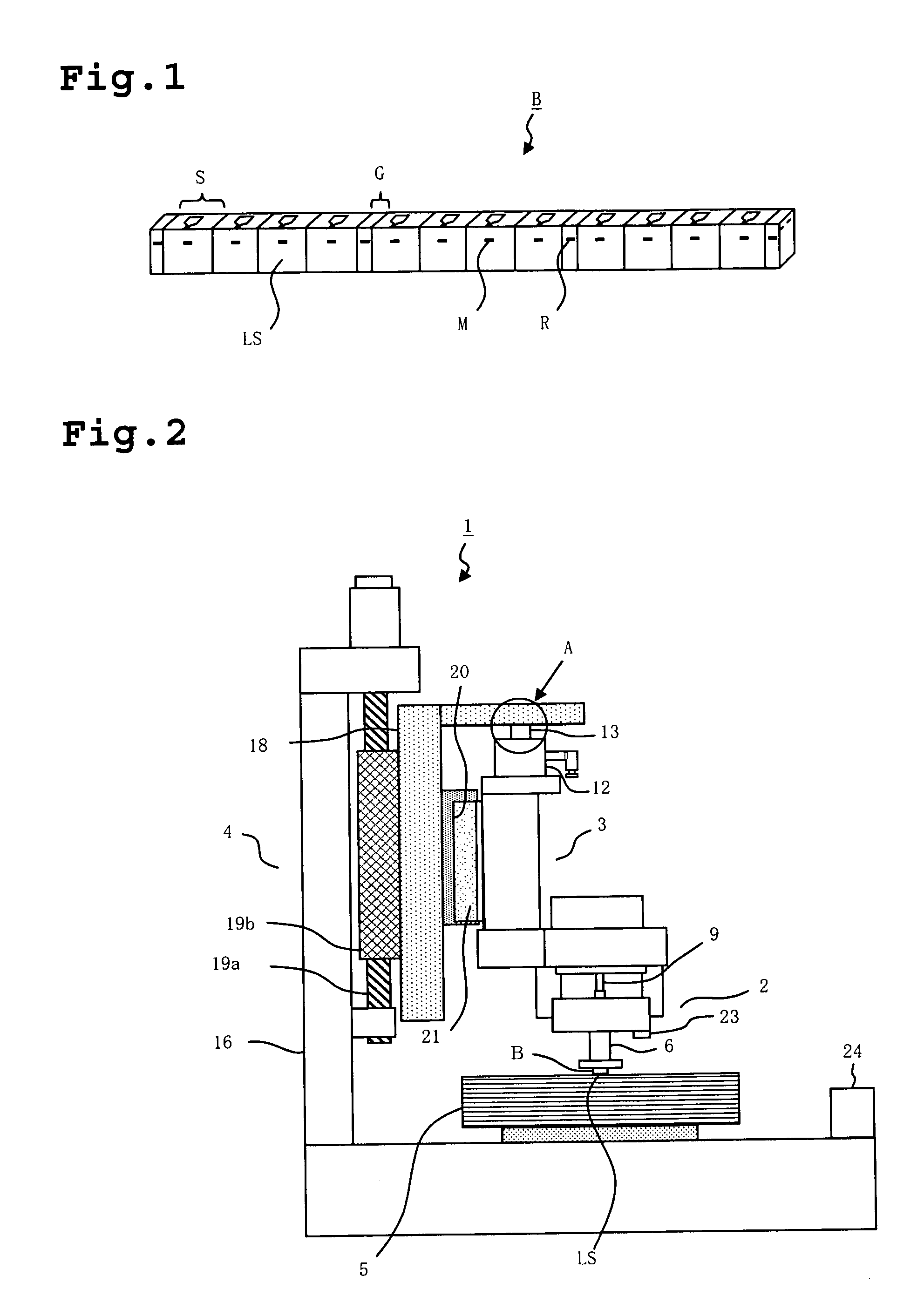
[0030]First, explanation will be made about elements that are to be lapped in accordance with the present embodiment. FIG. 1 is a perspective view showing a bar having a number of elements that are to be formed into sliders formed thereon. Bar B is fabricated by dicing a wafer to separate a part of elements S formed thereon. Each element S includes MR element M, which is a read element. MR elements M are positioned on the air bearing surface and are lapped with a predetermined element height. Therefore, the air bearing surface on which MR elements M are formed corresponds to lapping surface LS of bar B. Elements S are arranged in a line and gap G is formed between adjacent elements S. Gap G is provided with RLG element R that faces lapping surface LS. RLG element may have the same film structure as MR element M, and...


PUM

PropertyMeasurementUnit
heightaaaaaaaaaa
thicknessaaaaaaaaaa
widthaaaaaaaaaa

Abstract

An apparatus for lapping a slider comprises a lapping head for supporting elements while pressing the elements against a rotating lapping plate, the elements that are to be formed into sliders, a holding mechanism for supporting the lapping head, the holding mechanism having a first engaging member that extends in a vertical direction, a base for supporting the holding mechanism, the base having a second engaging member that extends in the vertical direction, wherein the second engaging member is engaged with the first engaging member to form an internal space therebetween, and a decompressing mechanism for decompressing the internal space. The holding mechanism is subjected to vertically upward force from the decompressed internal space in order to be movably supported by the base in the vertical direction.

Description

[0001]The present application is based on, and claims priority from, J.P. Application No. 2007-78685, filed on Mar. 26, 2007, the disclosure of which is hereby incorporated by reference herein in its entirety.BACKGROUND OF THE INVENTION[0002]1. Field of the Invention[0003]The present invention relates to an apparatus and a method for lapping a slider, and more particularly relates to an apparatus and a method for lapping a slider which is used in a surface finishing lapping process that is performed after an element height forming lapping process.[0004]2. Description of the Related Art[0005]Sliders used in hard disk drives are fabricated through a wafer process in which read elements and write elements are formed, a process for dicing the wafer into blocks or bars, a lapping process for forming a predetermined air bearing surface, and so on. The lapping process usually consists of two or three separate lapping processes.[0006]First, a rough lapping process, which is may be omitted, ...

Claims


Application Information

Patent Timeline
Patent Type & Authority Applications(United States)
IPC IPC(8): B24B25/00B24B1/00B24B37/04B24B37/30G11B5/31G11B5/60
CPCB24B37/048Y10T29/49048Y10T29/49036
Inventor ABE, KIYOHIKOKOBAYASHI, MASASHITSUCHIYA, HIROYASUTAN, SANTOSOWEI, ZHONG XIANZHANG, CHUN HUALI, FA HONGCHEN, MING YUAN
Owner SAE MAGNETICS (HK) LTD
Why Eureka
Try Eureka