
Screwdriver for bone screws

a screwdriver and bone screw technology, applied in screwdrivers, medical science, surgery, etc., can solve the problems of difficult cleaning and considerable work expenditure, and achieve the effect of safe operation

Inactive Publication Date: 2008-10-02
STRYKER EURO OPERATIONS HLDG LLC
View PDF17 Cites 40 Cited by
  • Summary
  • Abstract
  • Description
  • Claims
  • Application Information

AI Technical Summary

Benefits of technology

[0005]The invention has as one aspect to create a screwdriver which avoids the aforementioned disadvantages and which allows safe operation by the surgeon.
[0007]The screwdriver according to the invention is provided for bone screws, especially for compression screws and locking screws on bone nails. The screwdriver has a preferably longitudinal handle, with a shaft centrally extending out from the handle. A screw driving tool is provided on the free end thereof to match the drive on the screw. The shaft has a flexible shaft portion. According to a preferred embodiment of the invention, the shaft has two rigid portions provided on both sides of the flexible shaft portion. Preferably, the flexible shaft portion has on each of its two ends one holding portion, respectively, and a flexible element held between them. Preferably, the flexible element consists of a flexible tube element or of a helically coiled wire. At least the flexible shaft portion is surrounded by an elastic protection tubular cover or hose. The arrangement of the flexible shaft portion between two rigid shaft portions allows for a safe and precise handling, the surgeon having good control over the torque exerted. The flexible shaft portion with a flexible element creates the possibility for continuous bending of the shaft. The elastic protection hose, arranged at least across the elastic shaft portion, prevents the intrusion of blood and tissue into the flexible shaft portion and thus facilitates cleaning and disinfection of the screwdriver after use.
[0012]For better handling of the screwdriver, it has proven to be particularly advantageous that the flexible portion has a length which accounts for less than half of the total length. Preferably, the length of the flexible portion with respect to the total length is longer than one third of the total length, however.

Problems solved by technology

With this drill, it has proven to be disadvantageous because it is hard to manipulate, especially when used as a screwdriver, and that it is difficult to clean after using thus requiring considerable expenditure of work.

Method used


Image

  • Screwdriver for bone screws
  • Screwdriver for bone screws

Examples


Embodiment Construction

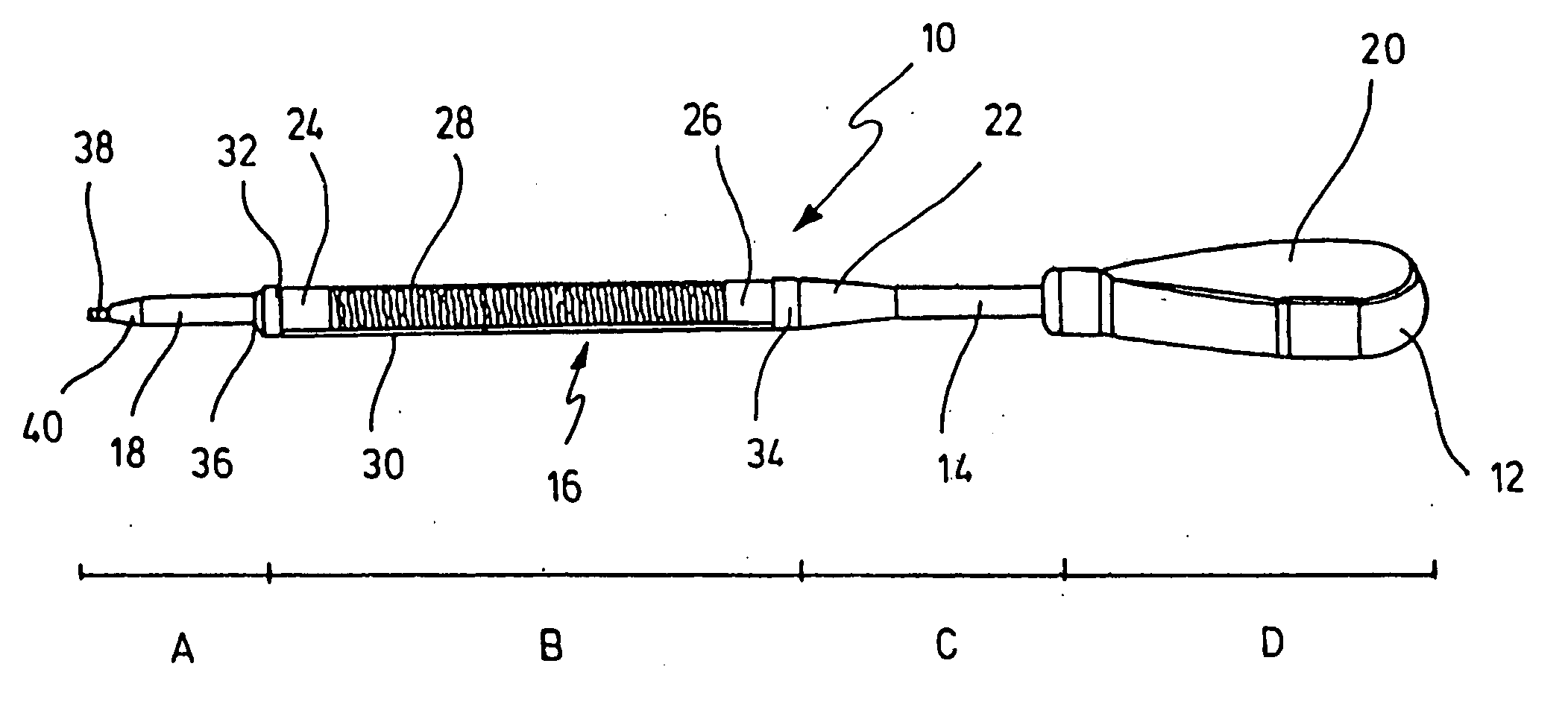
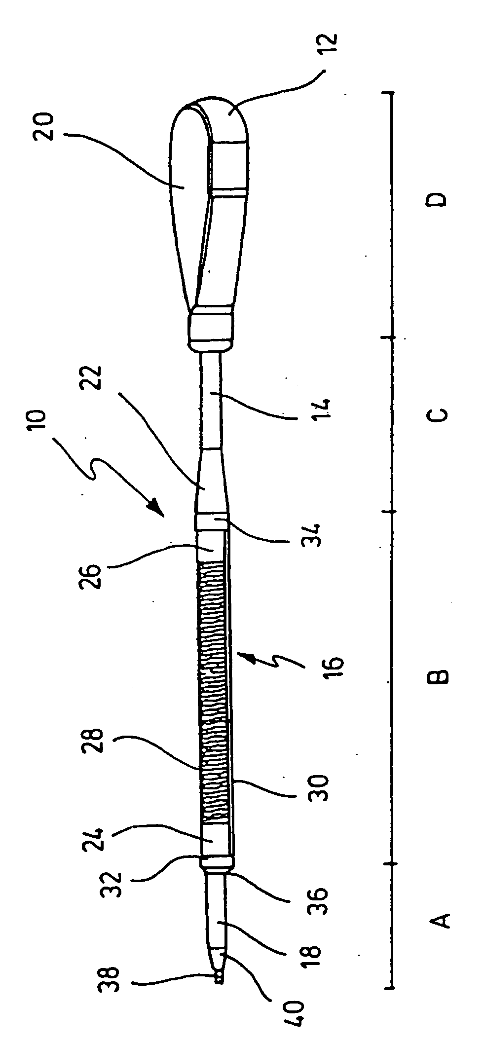
[0017]The single FIGURE shows a medical screwdriver 10, with a handle 12, a first rigid shaft portion 14, a flexible shaft portion 16 and a second rigid shaft portion 18. The handle 12 has a flattened side 20, which extends along the longitudinal axis of the shaft. The rigid and massively realised, preferably solid, shaft portion 14 juts out of the handle 12, the diameter of which increases conically upon the transition to the flexible portion 16 in a region 22.

[0018]The flexible portion 16 has on its two ends one holding portion 24 and 26, respectively, between which a helically coiled wire, from spring steel e.g., is held. A protective hose 30 of elastic, biocompatible material is drawn on the portions 24 and 26 as well as over the flexible wire. In the represented preferred example, the protective hose is a hose from silicone material, having a wall thickness of approximately 2 mm.

[0019]Besides the represented variant, in which the flexible region 28 is made from a helically coil...


PUM


Abstract

A screwdriver for bone screws, especially for compression screws and locking screws, has a handle and shaft extending out centrally from the handle. The shaft has a screw-driving tool on its free end. The shaft, includes a flexible shaft portion, wherein the shaft has two rigid, solid portions on both sides of the flexible portion. The flexible shaft portion has a flexible element for the transmission of a torque, and at least the flexible shaft portion is surrounded by an elastic protection hose or a rubber or plastic elastomeric tubular cover.

Description

CROSS-REFERENCE TO RELATED APPLICATION[0001]This application is a continuation of U.S. application Ser. No. 10 / 990,243, filed on Nov. 16, 2004, the disclosure of which is incorporated herein by reference.BACKGROUND OF THE INVENTION[0002]The present invention relates to a screwdriver for bone screws, especially for compression screws and locking screws on a bone nail. More particularly the invention relates to a flexible screw driver for use in surgery.[0003]From DD 238 724 A1, a medical screwdriver is known, which embraces a screw head with positive and non-positive fit.[0004]From DE 101 18 570 A1, a surgical drill is known, the shaft of which has a central longitudinal bore for a fibre-optical position transmitting device. The shaft of the drill has a clutch, upon which a drill head can be placed, a flexible shaft portion made from coiled spring steel directly adjoining to the clutch and a rigid shaft portion connected to the flexible shaft portion. A longitudinal continuous bore e...

Claims


Application Information

Patent Timeline
Patent Type & Authority Applications(United States)
IPC IPC(8): A61B17/58B25B15/00A61B17/88
CPCA61B17/8875
Inventor PRAGER, RONALDVOLZOW, STEFAN
Owner STRYKER EURO OPERATIONS HLDG LLC
Features
  • Generate Ideas
  • Intellectual Property
  • Life Sciences
  • Materials
  • Tech Scout
  • Unparalleled Data Quality
  • Higher Quality Content
  • 60% Fewer Hallucinations
Learn More