Insertion system for corneal implants

Inactive Publication Date: 2008-10-02
REVISION OPTICS
View PDF99 Cites 42 Cited by
  • Summary
  • Abstract
  • Description
  • Claims
  • Application Information

AI Technical Summary

Benefits of technology

[0007]In an embodiment, the corneal implant is preloaded in the holding space of the inserter and the preloaded inserter is stored in a storage container filled with storage fluid, e.g., saline, until use. In one embodiment, a cap is placed on the distal end of the inserter after the implant is preloaded. The cap encloses the holding space of the inserter to prevent the corneal implant from moving out of the holding space in the storage fluid during storage. By preloading the implant in the inserter, the surgeon does not have to separately retrieve the implant and place the implant in the inserter, which is difficult due to the small size and delicate nature of the implant.
[0008]A method of delivering a corneal impla

Problems solved by technology

As is well known, abnormalities in the human eye can lead to vision impairment.
Some typical abnormalities include variations in the shape of the eye, which can lead to myopia (near-sightedness), hyperopia (far-sightedness) and astigmatism as well as variations in the tissue present throughout the eye

Method used


Image

  • Insertion system for corneal implants
  • Insertion system for corneal implants
  • Insertion system for corneal implants

Examples


Embodiment Construction

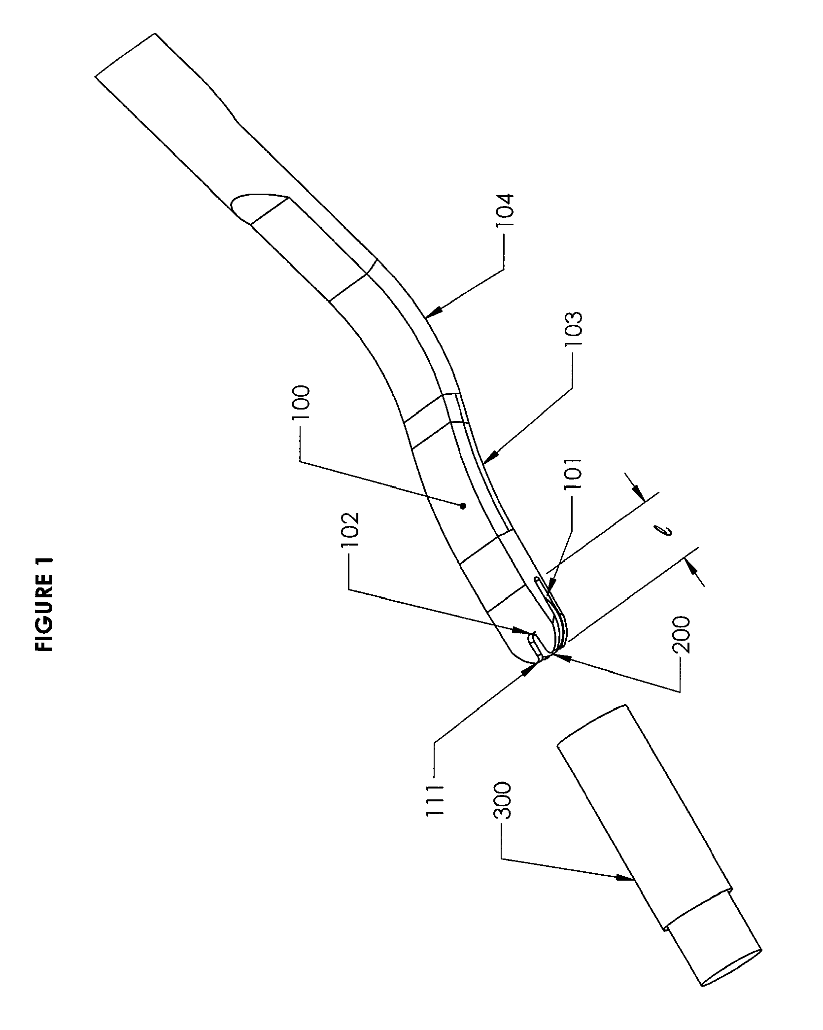
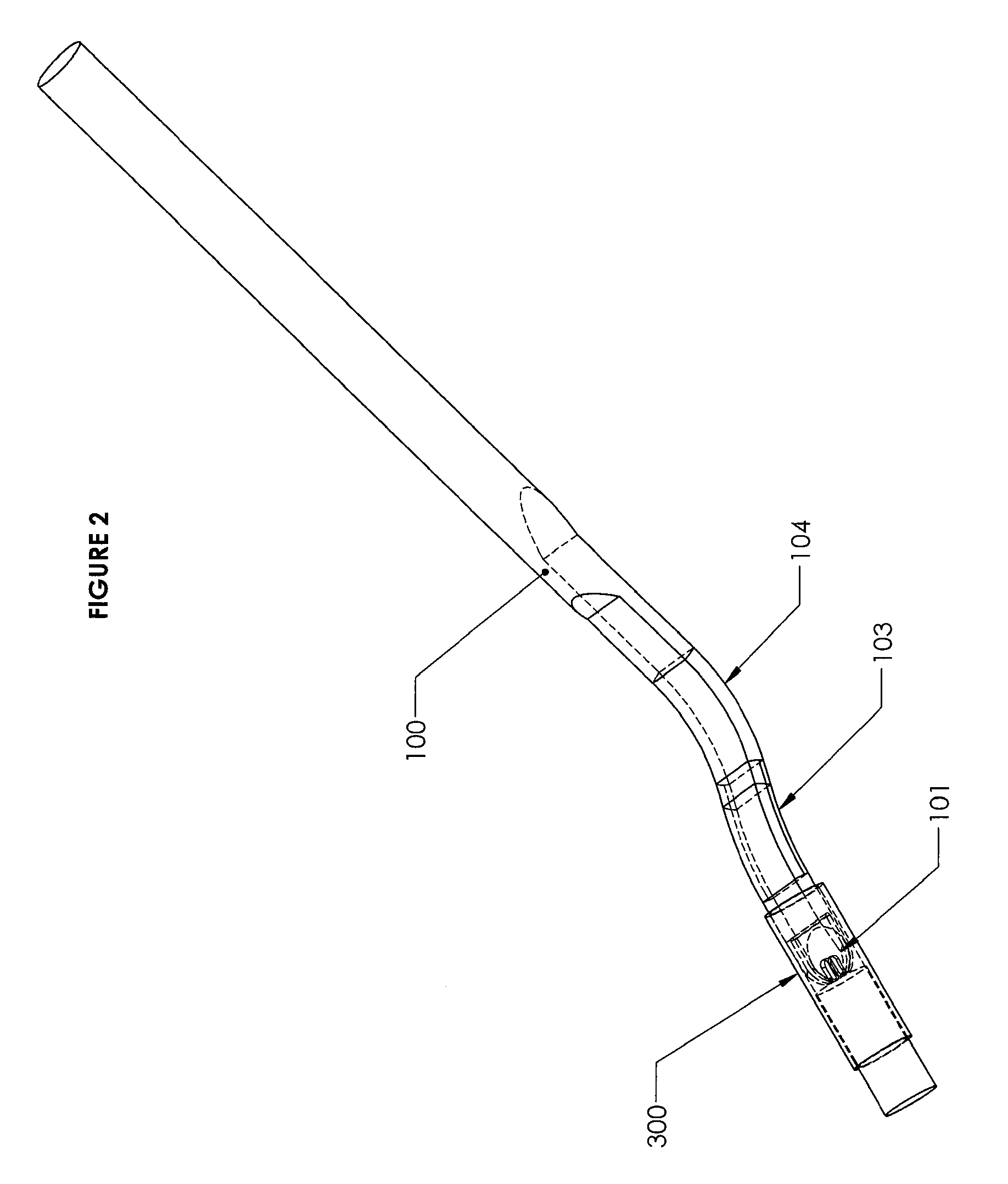
[0024]FIGS. 1-5 show an insertion system according to an embodiment that is particular suited for delivering a corneal implant, e.g., inlay, in or on the cornea. The insertion system is also suited for storing the implant prior to its use. The insertion system includes an inserter 100 having an elongated body, which may be made of titanium, stainless steel, plastic, or other biocompatible material. The inserter 100 comprises a distal portion having generally flat top and bottom surfaces. The distal portion of the inserter 100 includes a clearance bend 104 where the inserter is bent to provide clearance between the inserter and a patient's facial features (e.g., nose, cheeks, etc.) as explained further below. The distal portion of the inserter 100 also includes a curved portion 103 that is contoured to follow the shape of a patient's cornea as explained further below. The curved portion 103 is concaved on the bottom surface of the inserter 100.

[0025]The inserter 100 further includes ...


PUM


Abstract

Provided therein are apparatuses, systems and methods for storing and retrieving a corneal implant and for delivering the corneal implant in or on the cornea. In an embodiment, a insertion system comprises an inserter for delivering a corneal implant to a desired location in or on the cornea. The inserter has a holding space at its distal end for holding a corneal implant therein. A solution may substantially fill the holding space with the corneal implant to keep the implant hydrated and to hold the implant in the holding space by the surface tension of the solution. The corneal implant may be preloaded in the holding space of the inserter and stored in a storage container filled with storage fluid, e.g., saline, until use. To deliver the corneal implant, the inserter is positioned at the desired location, and the corneal implant released from the holding space of the inserter.

Description

FIELD OF THE INVENTION[0001]The field of the invention relates generally to corneal implants, and more particular, to insertion systems for corneal implants.BACKGROUND INFORMATION[0002]As is well known, abnormalities in the human eye can lead to vision impairment. Some typical abnormalities include variations in the shape of the eye, which can lead to myopia (near-sightedness), hyperopia (far-sightedness) and astigmatism as well as variations in the tissue present throughout the eye, such as a reduction in the elasticity of the lens, which can lead to presbyopia. A variety of technologies have been developed to try and address these abnormalities, including corneal implants.[0003]Corneal implants can correct vision impairment by altering the shape of the cornea. Corneal implants can be classified as an onlay or an inlay. An onlay is an implant that is placed over the cornea such that the outer layer of the cornea, e.g., the epithelium, can grow over and encompass the implant. An inl...

Claims


Application Information

Patent Timeline
IPC IPC(8): A61F2/14
CPCA61F2/146A61F2/148
Inventor DISHLER, JONSCHNEIDER, NEDLE, ALAN NGOC
Owner REVISION OPTICS
Why Eureka
Try Eureka