
Vascular hemostasis device and deployment apparatus

a hemostasis device and hemostasis technology, applied in the field of vascular hemostasis devices and deployment apparatuses, can solve the problems of prolonged personal attention of healthcare professionals, prone to reopen unexpectedly wound closures, and pain in the procedur

Active Publication Date: 2008-10-02
ST JUDE MEDICAL +1
View PDF39 Cites 147 Cited by
  • Summary
  • Abstract
  • Description
  • Claims
  • Application Information

AI Technical Summary

Benefits of technology

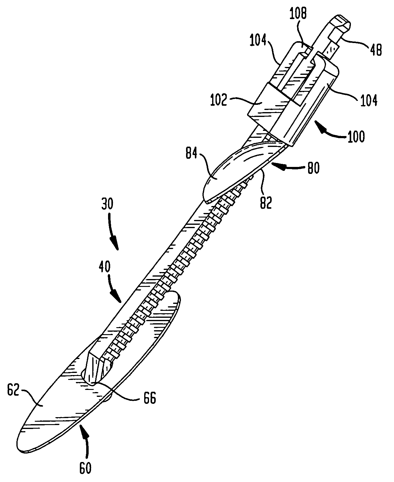
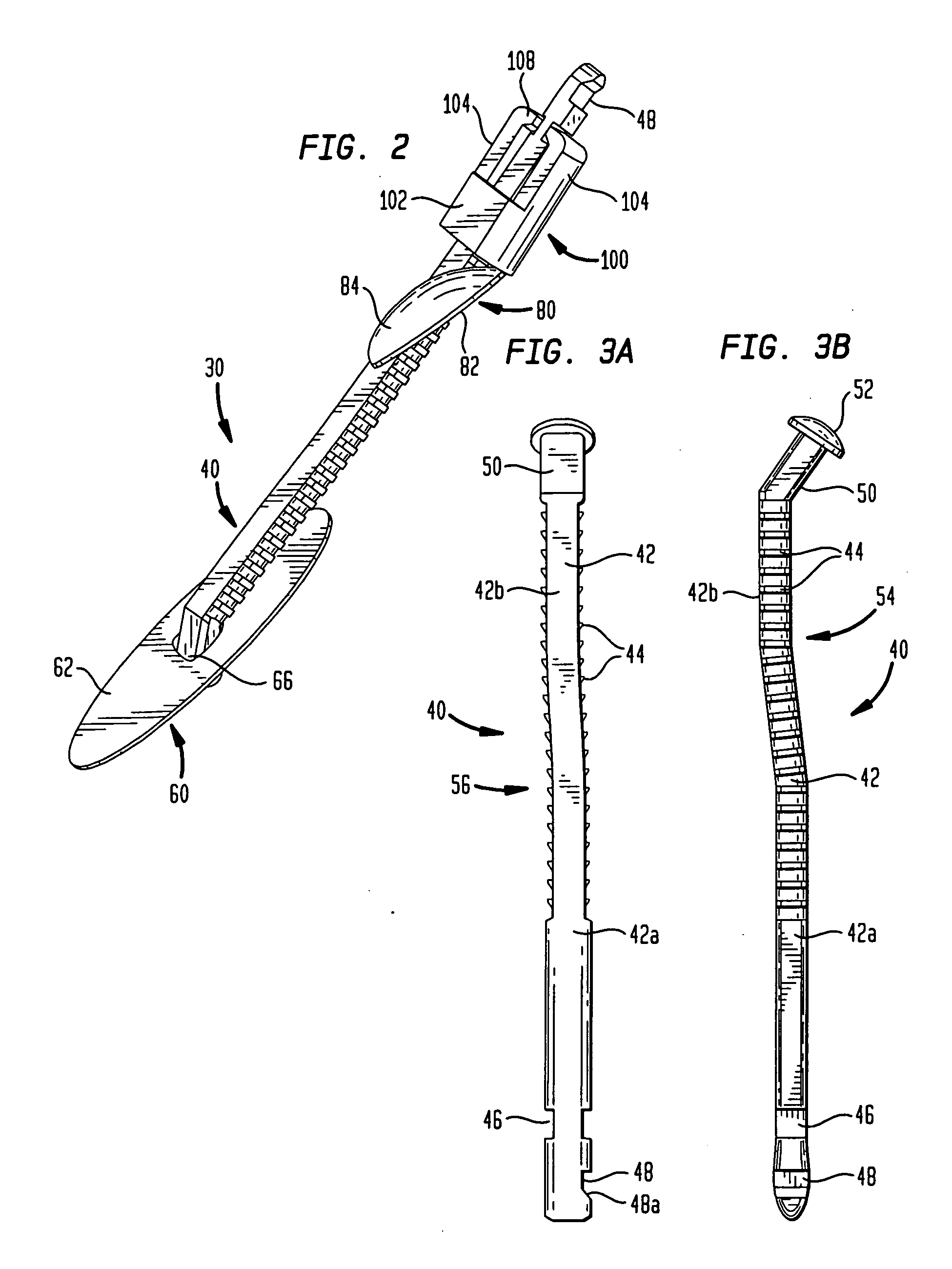
[0027]In a highly preferred embodiment hereof, at least one of the sidewalls may define an elongated hub travel slot extending in the longitudinal direction, and the hub may include at least one arm projecting laterally from the hub into the hub travel slot, whereby the hub travel slot defines an extent of movement of the hub in the longitudinal direction. Preferably, the actuator is movable through a movement path, and the hub is movable in the longitudinal direction between an initial position in which the at least one arm of the hub is positioned in the movement path of the actuator to prevent the actuator from moving the drive block, and a tension position in which the at least one arm of the hub is positioned outside of the movement path of the actuator to permit the actuator to move the drive block. More preferably, the hub is moved to the tension position when the tensioning system applies a predetermined tension to the rigid post. The movement of the hub from the initial position to the tension position may move the coupling assembly in the longitudinal direction toward the distal end of the housing. When the hub is in the tension position, the recess of the at least one deployment link may be aligned to receive the at least one boss of the drive block.

Problems solved by technology

Because of the pressure required, the time during which it must be applied and the need for immobilization, the procedure is painful and uncomfortable.
It also requires the prolonged personal attention of a healthcare professional.
Finally, wound closures accomplished in this matter are prone to reopen unexpectedly long after closure appears to have been completed.
Since sealing can be such a problem, cardiologists tend to use the smallest caliber catheters when performing catheterization procedures.

Method used


Image

  • Vascular hemostasis device and deployment apparatus
  • Vascular hemostasis device and deployment apparatus
  • Vascular hemostasis device and deployment apparatus

Examples


Embodiment Construction

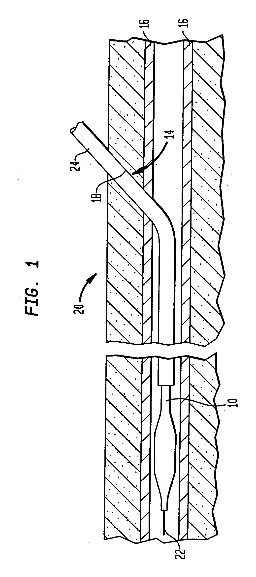
[0047]In certain procedures, for example, intra-aortic balloon pumping (“IABP”), percutaneous transluminal coronary angioplasty (“PTCA”) and angiography, as best seen in FIG. 1, a catheter or other medical device 10 is inserted into a blood vessel or artery 16, typically using what is commonly known as the Seldinger technique. In accordance with this technique, a hollow needle (not shown) is inserted through the skin into the blood vessel or artery 16, most frequently the common femoral artery in the groin area of the patient's leg 20, thereby creating a puncture wound 14. Puncture wound 14 includes a tissue channel 18 extending through a layer of tissue separating blood vessel 16 from the patient's skin. A guide wire 22 is then inserted through the needle and advanced to the desired area. Keeping the guide wire 22 in place, the needle is removed and discarded. A dilator / insertion sheath set is then advanced over the guide wire and inserted into the blood vessel to dilate the punctu...


PUM


Abstract

A hemostasis device for percutaneously sealing a puncture in the wall of a blood vessel includes a rigid post, and a foot, a seal and a retaining member mounted on the rigid post. The hemostasis device may be deployed in the puncture so that the foot is positioned within the blood vessel. Tension is applied to the rigid post to hold the foot against the inside surface of the blood vessel. The retaining member is then pushed along the length of the rigid post, advancing the seal to a deployed state against the outside surface of the blood vessel. The puncture in the blood vessel is sandwiched between the foot and the seal in the deployed state. The rigid post, foot, seal and retaining member may all be formed from a resorbable polymeric material.

Description

CROSS REFERENCE TO RELATED APPLICATIONS[0001]This application claims the benefit of the filing date of U.S. Provisional Application No. 60 / 920,640, filed on Mar. 29, 2007, the disclosure of which is hereby incorporated by reference herein.BACKGROUND OF THE INVENTION[0002]The present invention relates to devices for sealing puncture wounds in blood vessels caused by any one of a number of medical procedures, and to methods for sealing such puncture wounds using the device.[0003]In certain medical procedures, such as cardiac catheterization, dilation and counterpulsation, a catheter or other device is inserted in an artery, most commonly by percutaneous methods, and then fed through the arterial tree to the site where needed, frequently, the region of the heart. The site usually selected for insertion is the groin, because the femoral artery in that region is relatively easy to locate.[0004]These procedures are normally initiated by the insertion of an angiographic needle, followed by...

Claims


Application Information

Patent Timeline
IPC IPC(8): A61B17/08
CPCA61B17/0057A61B2017/00407A61B2017/00637A61B2017/00654A61B2017/00659
Inventor BATES, JAMES S.HINCHLIFFE, PETER
Owner ST JUDE MEDICAL
Learn More