Pseudorandom number generator and encrytion device using the same

a technology of pseudonym and encrytion device, which is applied in the direction of digital transmission, instruments, securing communication, etc., can solve the problems of large amount of memory and limited downsizing, and achieve the effect of reducing linear transformation and reducing siz

Active Publication Date: 2008-10-02
HITACHI LTD
View PDF4 Cites 7 Cited by
  • Summary
  • Abstract
  • Description
  • Claims
  • Application Information

AI Technical Summary

Benefits of technology

[0009]Thus, it is desired to develop a pseudorandom number generation technology that makes it possible to implement with a smaller circuit scale and a smaller amount of memory, which is suitable for small electronic devices.
[0014]According to the present invention, it is possible to reduce the linear transformation, and thus to provide a pseudorandom number generator reduced in size as a whole.

Problems solved by technology

Further, a large amount of memory is necessary to implement the large-scale high-density substitution by software.
For this reason, the downsizing is limited in the implementation of the pseudorandom number generation method described in Patent document 1.

Method used


Image

  • Pseudorandom number generator and encrytion device using the same
  • Pseudorandom number generator and encrytion device using the same
  • Pseudorandom number generator and encrytion device using the same

Examples


embodiment

[0040]Hereinafter, an embodiment of the present invention will be described with reference to accompanying drawings.

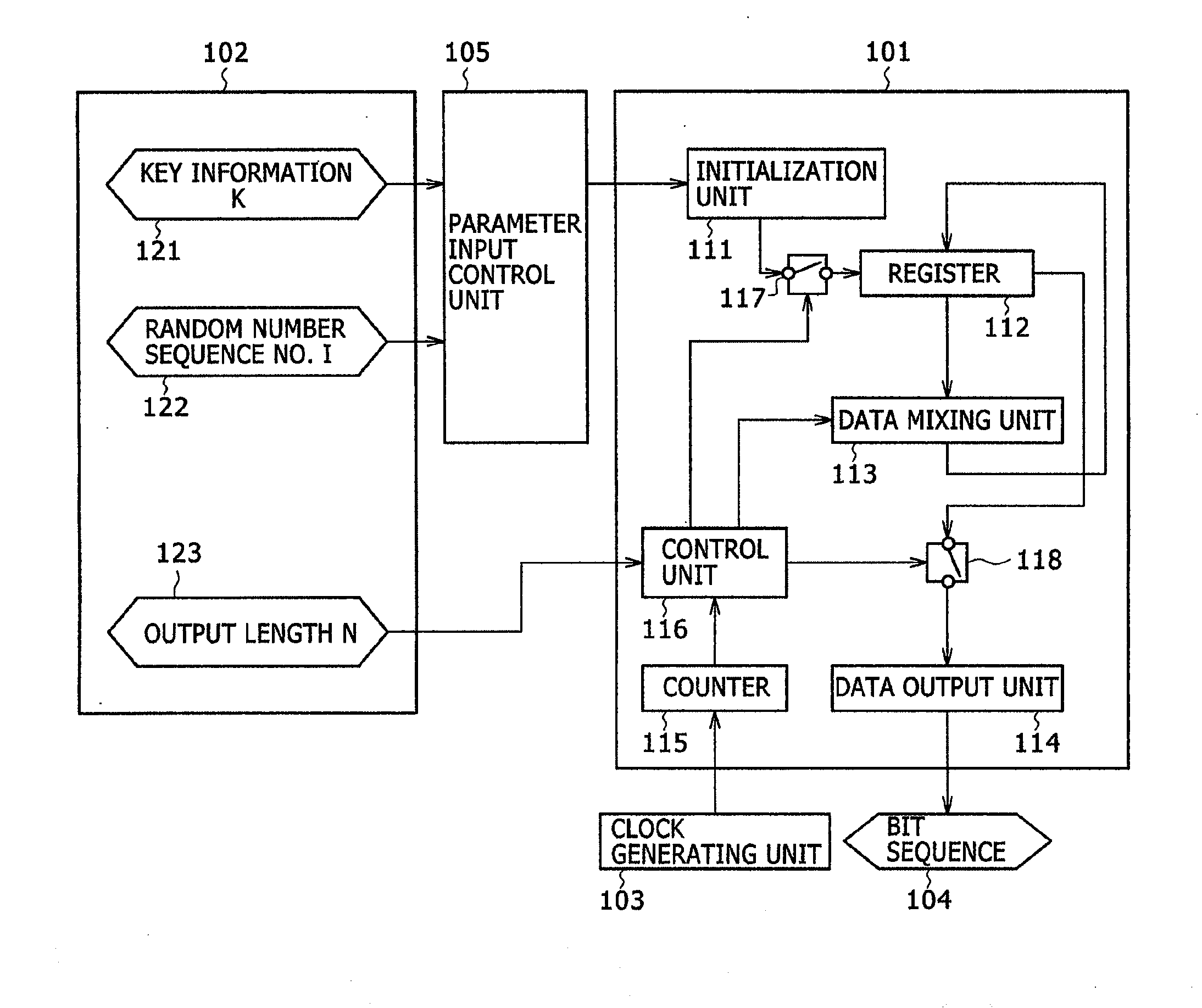
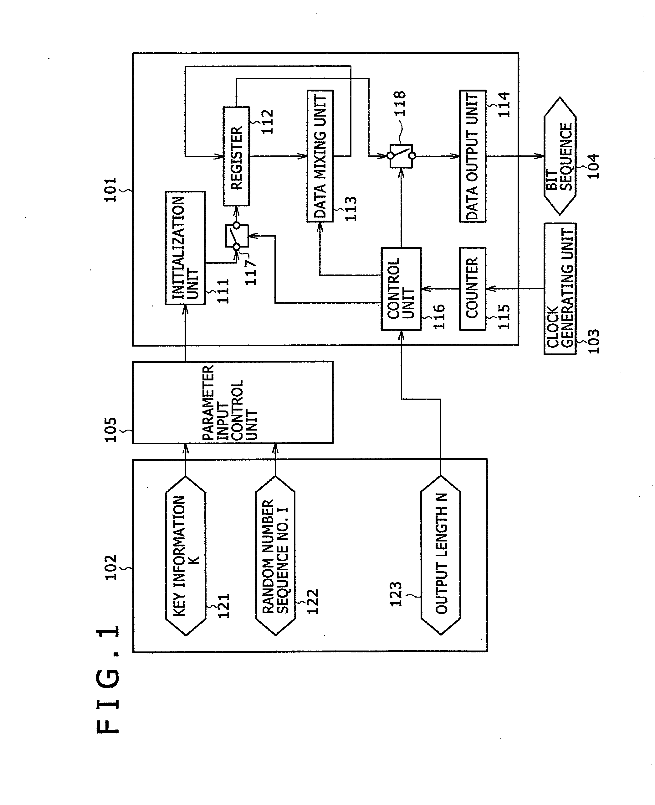
[0041]FIG. 1 is a schematic diagram showing a functional configuration of a pseudorandom number generator (pseudorandom number generating unit) in the embodiment. The configuration of the pseudorandom number generator will be described below with reference to FIG. 1.

[0042]A pseudorandom number generator (101) receives input data (102), as an external input, including key information (121) and a random number sequence number (122) through a parameter input control unit (105), in addition to an output length (123). The parameter input control unit (105) checks whether the input is invalid, and then inputs the key information (121) and the random number sequence number (122) into an initialization unit (111). The output length (123) is input to a control unit (116). For example, when the input key information (121) and random number sequence number (122) are too large or ...


PUM


Abstract

A pseudorandom number generator reduced in size while maintaining high security is disclosed. The generator has a state storage unit of 2 blocks (n bits per block) and a buffer of plurality of blocks, and mixes their contents to obtain a random number sequence. The mixing is done by a nonlinear transformation unit for inputting the stored content of the buffer to output data of the same size as the input data, a first linear transformation unit for inputting the content of the state storage unit and the output of the nonlinear transformation unit to store an output into the state storage unit, and a second linear transformation unit for inputting the stored content of the buffer and the stored content of the state storage unit to store an output into the buffer. The mixed content of the state storage unit is output as a random number sequence.

Description

INCORPORATION BY REFERENCE[0001]This application claims priority based on Japanese patent applications, Nos. 2007-090214 filed on Mar. 30, 2007 and 2007-245710 filed on Sep. 21, 2007, the entire contents of which are incorporated herein by reference.BACKGROUND OF THE INVENTION[0002]The present invention relates to a device for generating a practical random number sequence and its application device.[0003]Random numbers are highly necessary for such purposes as signature generation using public key encryption technology, key generation for performing secret communication, and stream cipher technology.[0004]However, it is unrealistic to try to use true random numbers in such purposes, and pseudorandom numbers (hereinafter simply referred to as random numbers), which are generated by a pseudorandom number generating method or by a device using the method, are practically used.[0005]When used for encryption, the pseudorandom number is necessary to meet the requirement of properties rela...

Claims


Application Information

Patent Timeline
Patent Type & Authority Applications(United States)
IPC IPC(8): G06F7/58H04L9/06G06F17/14
CPCG06F7/582H04L9/0668H04L2209/12H04L2209/60
Inventor WATANABE, DAIYOSHIDA, HIROTAKA
Owner HITACHI LTD
Why Eureka
Try Eureka