
Civil Engineering Loading Machine

Inactive Publication Date: 2008-10-09
VOLVO COMPACT EQUIP
View PDF8 Cites 5 Cited by
  • Summary
  • Abstract
  • Description
  • Claims
  • Application Information

AI Technical Summary

Benefits of technology

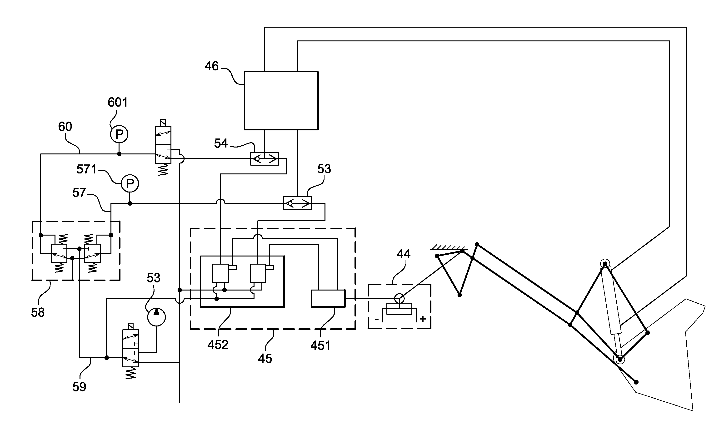
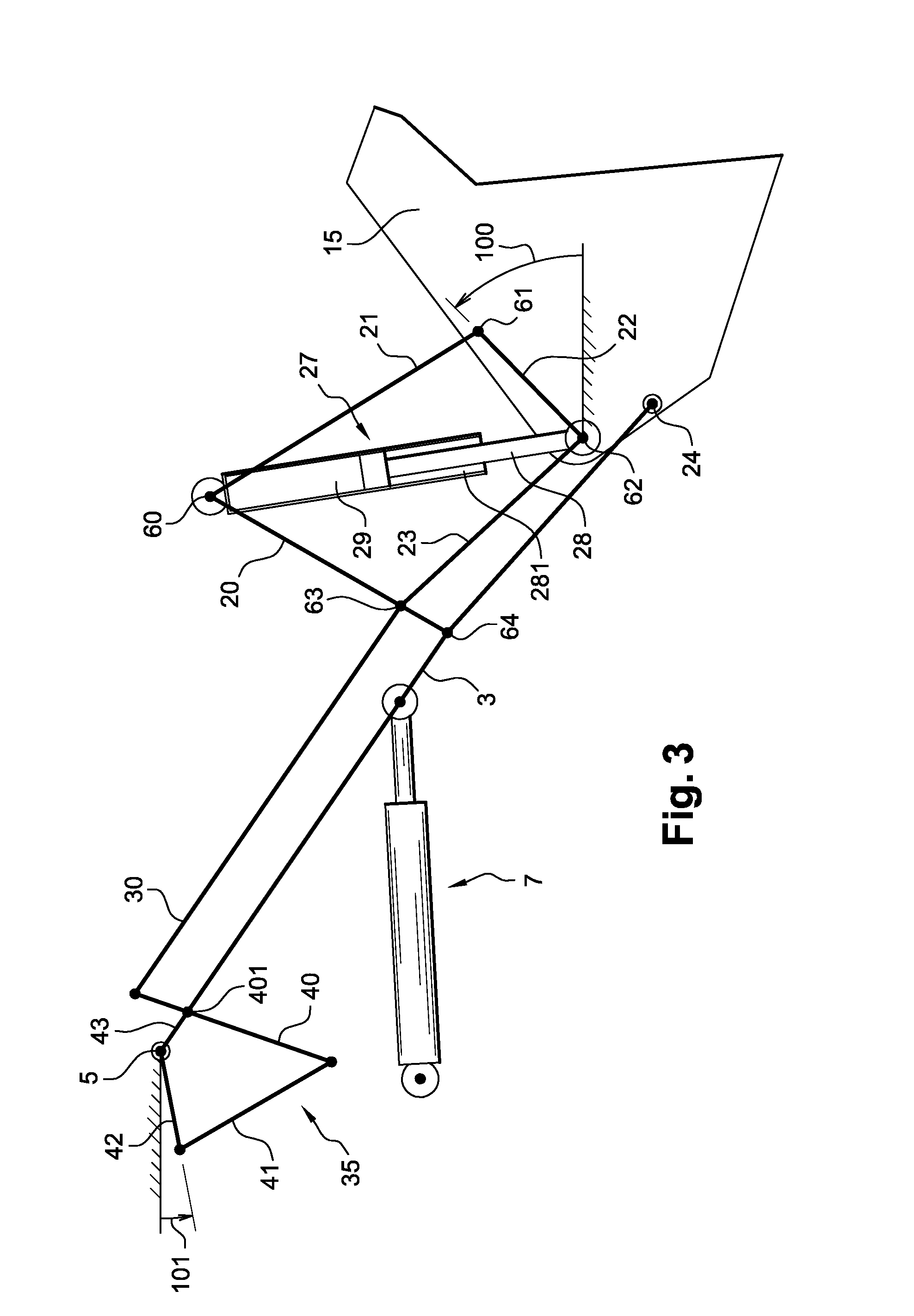
[0026]In other words, the machine that is the subject of the invention comprises a telltale mechanism that corresponds to a “copy” of the main working mechanism and which faithfully and mechanically imitates the movements of it, so that an angular sensor measures an inclination-image. This inclination-image is representative of the inclination of the working implement. Since the telltale mechanism is shifted closer to the chassis, it is less exposed to the elements causing deterioration or disruption of the inclination measurement. The inclination of the bucket is therefore controlled in a closed loop which provides advantages in terms of precision.
[0029]Advantageously, the telltale mechanism may be deformable under the mechanical action of a movement transmission member. In other words, this member mechanically sends information of the angle of inclination of the working implement relative to the chassis. This connecting bar causes the telltale mechanism to rotate. Such a member therefore makes it possible to faithfully transmit the movement of the deformable quadrilateral to the telltale mechanism and, consequently, to transmit the angle of inclination to be measured.
[0032]a hydraulic compensation device making it possible to generate an additional control pressure in order to move the implement cylinder according to the signal transmitted by the angular sensor,
[0033]a circuit selector capable of transmitting to the directional flow valve the higher of the control pressure delivered by the manipulator and the additional control pressure,so that the inclination of the working implement is kept generally constant irrespective of the controls applied by the driver on the manipulator. Therefore, the unexpected dumping of the goods is prevented, whether it is on the cabin side for materials contained a in a bucket or on the side external to the machine for goods installed on a pallet, which is likely to slip forward along forks that are overinclined.

Problems solved by technology

This is the case, for example, when the implement is a bucket loaded with materials that may risk inclining too much and consequently dumping its load unexpectedly, which may cause problems of safety, of material breakage and / or waste of time.
However, this device is not very adaptable to the various working implements that are likely to be mounted on the arm as required.
Otherwise the compensation of inclination is incorrect and the aforementioned problems may occur.
However, in such a device failures of the angular sensors may occur, particularly of the sensor situated close to the implement, because they are positioned at a distance from the chassis.
Specifically, they are therefore exposed to vibrations, to impacts and to elements causing deterioration or disruption of measurement such as rain, dust or mud, which may over time damage these angular sensors despite their sealed manufacture.
Consequently, these sensors may no longer operate at all or may operate erratically and, in consequence, transmit incorrect information.
In the same manner, the electric wires that connect these angular sensors to a computing unit or to an actuator to transmit the measurement signals are exposed to the same disruptive elements and therefore risk the same consequences.
In addition, the change of working implement there again poses an adaptation problem.

Method used


Image

  • Civil Engineering Loading Machine
  • Civil Engineering Loading Machine
  • Civil Engineering Loading Machine

Examples


Embodiment Construction

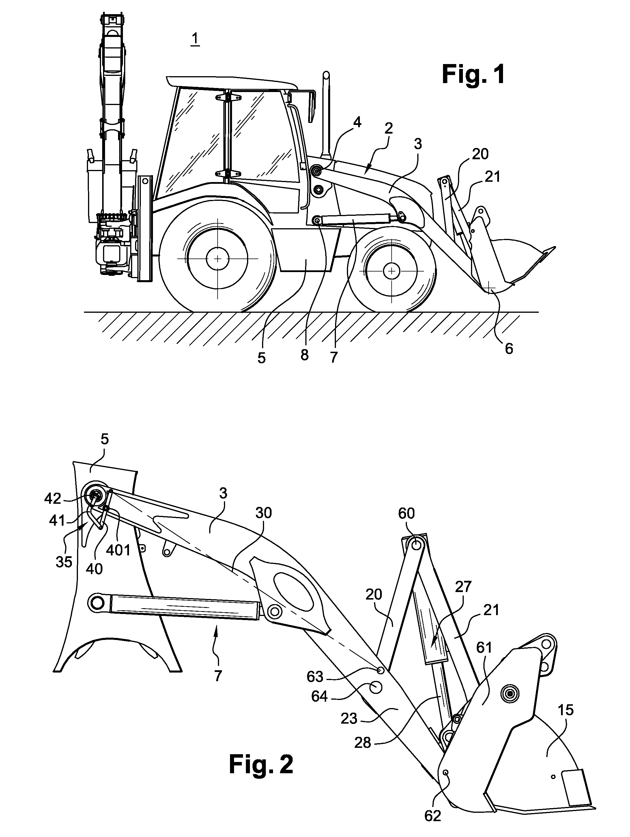
[0015]The invention therefore relates to a civil engineering machine of the “loader” type. Such a machine comprises a chassis and working equipment. The working equipment comprises:[0016]at least one arm that can move relative to the chassis,[0017]an arm cylinder, of which one end is connected to the arm and the other to the chassis, and capable of rotating the arm relative to the chassis,[0018]a working implement articulated relative to the arm,[0019]a main kinematic linkage forming, with a portion of the working implement and a portion of the arm, a main deformable mechanism,[0020]an implement cylinder capable of being controlled to cause the deformation of the main deformable mechanism in order to ensure the inclination of the working implement relative to the arm,[0021]a hydraulic control circuit allowing the implement cylinder to be supplied by means of a directional flow valve.

[0022]According to the invention, the working equipment also comprises:[0023]a secondary kinematic li...


PUM


Abstract

The invention relates to a civil engineering loading machine (1) provided with a frame (5) and working equipment (2) which comprises at least one arm (3), an arm actuator (7) for rotatably displacing said arm (3) with respect to the frame (5), a working tool (15) hingable with respect to the arm (3), a main cinematic chain (20, 21) forming together with the working tool (15) part and the arm (3) part a main deformable mechanism and a controllable tool actuator (27) for generating the deformation of the main deformable mechanism in such a way that the inclination angle (100) of the working tool (15) with respect to the arm (3) is provided. The inventive machine is characterized in that it also comprises a secondary cinematic chain (40, 41, 42, 43) forming together with the part of the arm (3), which is located in the area (4) of articulation thereof on the frame (5), a deformable reference mechanism (35) whose deformation directly corresponds to the inclination angle (100) of the working tool (15) with respect to the frame (5), an angle sensor (44) for measuring an angle (101) displaying the deformation of the reference mechanism (35) with respect to the frame (5) and a control device (45) which is connected to said sensor (44) and controls the feeding of the working tool actuator (27) and / or the arm actuator (7).

Description

TECHNICAL FIELD[0001]The invention relates to the field of civil engineering machines and more particularly to machines of the loader type. Its object is more precisely a device making it possible to measure the inclination of a mobile working implement of the machine. A particular application of the present invention makes it possible to automatically correct the inclination of the bucket during the various loading operations.PRIOR ART[0002]Usually, a civil engineering machine that makes it possible to pick up goods, such as materials, placed on the ground in order to dump them into a trailer body or into a truck or vice versa is called a “loader”. A loader therefore in a known manner comprises a chassis and particular working equipment. This working equipment usually includes an arm that is articulated relative to the chassis. This arm may be raised under the action of a cylinder usually called an “arm cylinder”.[0003]One of the ends of the arm receives a working implement, such a...

Claims


Application Information

Patent Timeline
IPC IPC(8): E02F3/43
CPCE02F3/432E02F3/433
Inventor FLOREAN, GILLES
Owner VOLVO COMPACT EQUIP
Learn More