
System for controlled fluid heating using air conditioning waste heat

a technology of air conditioning and waste heat, which is applied in the direction of compression machines with several condensers, light and heating apparatus, machine operation mode, etc., can solve the problems of equipment damage, cost of operation, commercial success, etc., and achieve the effect of optimum air conditioning system efficiency and without equipment damag

Inactive Publication Date: 2008-10-09
ORCUTT JOHN WALTER
View PDF4 Cites 39 Cited by
  • Summary
  • Abstract
  • Description
  • Claims
  • Application Information

AI Technical Summary

Benefits of technology

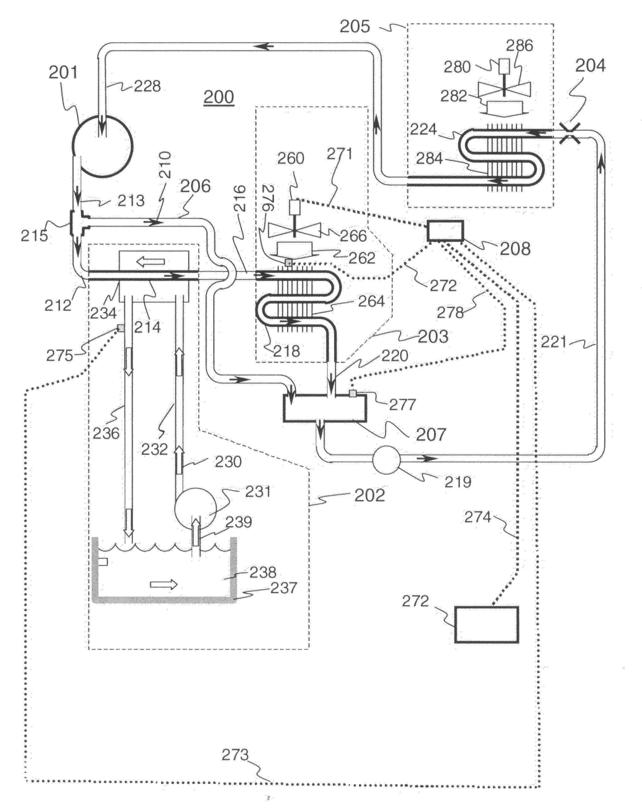
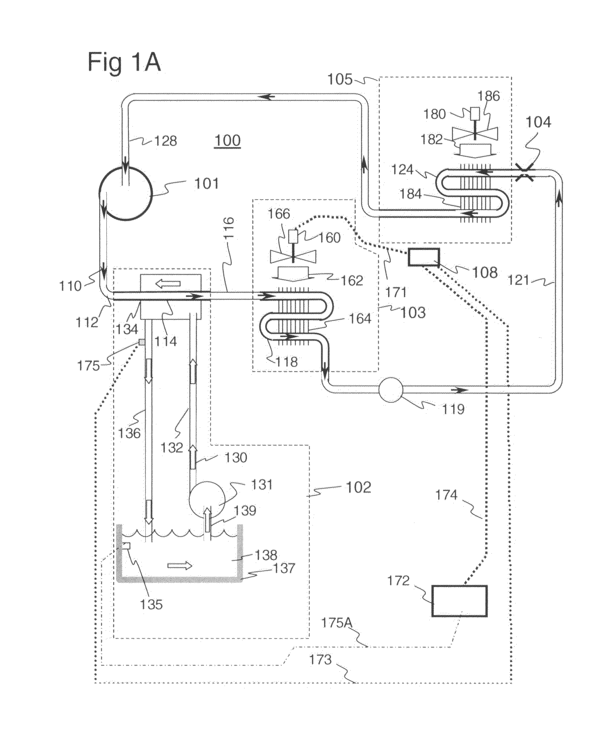
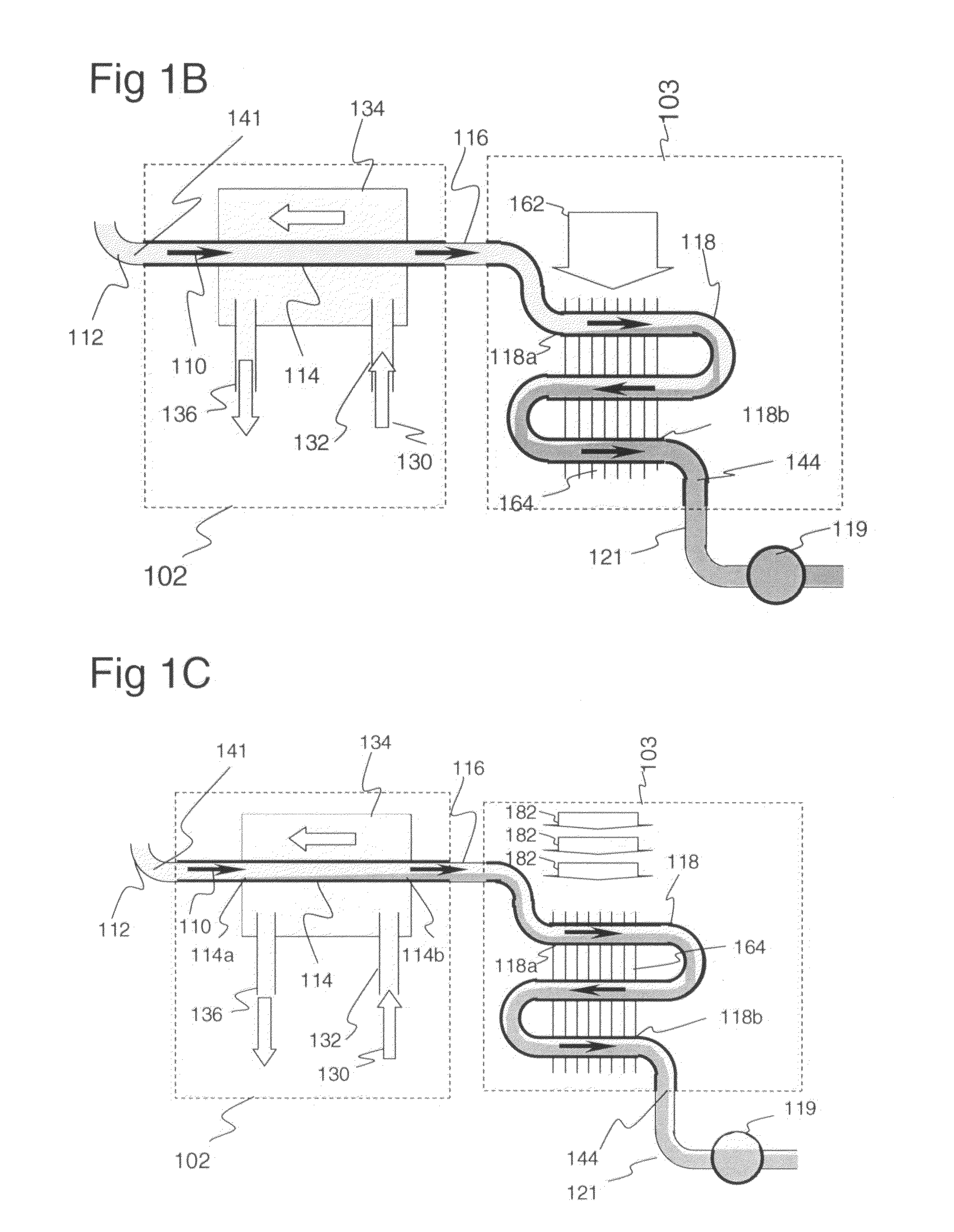
[0003]It is a general object of the present invention to provide a pool water heater that uses the waste heat from a refrigeration or an air conditioning system to heat pool water, or other fluids, to useful and desired temperatures, and to do such water heating with consistent, controlled output water temperatures, with optimum air conditioning system efficiency, and without equipment damage.

Problems solved by technology

Many existing systems use electric, gas, or fuel oil-heating units, which are costly to operate.
Attempts to utilize air conditioning waste heat to provide a safe, economical, and low energy consuming pool water heating system, such as shown in U.S. Pat. No. 3,976,123 issued to Davies, have not been commercially successful as previous systems did not maintain a constant discharge temperature, were inefficient to operate, and could cause equipment damage.

Method used


Image

  • System for controlled fluid heating using air conditioning waste heat
  • System for controlled fluid heating using air conditioning waste heat
  • System for controlled fluid heating using air conditioning waste heat

Examples


Embodiment Construction

[0014]The use of air conditioning waste heat to heat swimming pool water has been demonstrated and is well know in the art. Davies discloses a system for controlled heating of pool water using waste heat of an air conditioner where the refrigerant-to-air condenser fan is cycled on and off in response to a sensor monitoring the temperature of the water exiting the refrigerant-to-water condenser. If the water temperature is below the Fan Off Set Point, the air conditioning condenser fan will be turned off, increasing the condensing pressure and temperature, increasing the amount of heat going into the refrigerant-to-water condenser, increasing the temperature of the water exiting refrigerant-to-water condenser. When the water temperature reaches the Fan On Set Point, which is higher than the Fan Off Set Point, the air conditioning fan will be turned on, decreasing the condensing pressure and temperature, reducing the amount of heat going into the refrigerant-to-water condenser, loweri...


PUM


Abstract

A system is disclosed which utilizes air conditioning waste to heat a second fluid such as swimming pool water. The second condenser for pool water heating is connected in parallel with the air conditioning condenser. An accumulator is connected between the condensers and the expansion valve to absorb fluctuations in refrigerant level due to different operating conditions caused by the pool water heating, thereby ensuring that liquid refrigerant is always supplied to the expansion valve. A controller reads the ambient air temperature at the air conditioning condenser and reads the air conditioning system condensing pressure and uses an algorithm to compute ambient air fan speed at the air conditioning condenser based on these two inputs to maintain a consistent heated pool water temperature.An alternate system includes first and second condensers connected in series with an accumulator connected between the second condenser and the expansion valve and a pressure equalization line connected between the compressor and the accumulator. A controller reads the ambient air temperature at the air conditioning condenser and reads the air conditioning system condensing pressure and uses an algorithm to compute ambient air fan speed at the air conditioning condenser based on these two inputs to maintain a consistent heated pool water temperature.

Description

TECHNICAL FIELD[0001]The present invention relates to the recovery of waste heat from a refrigeration or an air conditioning system, to provide a heated fluid at a controlled, consistent temperature.BACKGROUND[0002]The use of a heater to warm swimming pool water is quite common among swimming pool owners. Many existing systems use electric, gas, or fuel oil-heating units, which are costly to operate. Attempts to utilize air conditioning waste heat to provide a safe, economical, and low energy consuming pool water heating system, such as shown in U.S. Pat. No. 3,976,123 issued to Davies, have not been commercially successful as previous systems did not maintain a constant discharge temperature, were inefficient to operate, and could cause equipment damage.SUMMARY OF THE INVENTION[0003]It is a general object of the present invention to provide a pool water heater that uses the waste heat from a refrigeration or an air conditioning system to heat pool water, or other fluids, to useful ...

Claims


Application Information

Patent Timeline
IPC IPC(8): F25B27/02
CPCF24D2200/24F25B6/04F25B49/027F25B2339/047F25B2400/0403Y02B30/52F25B2600/111F25B2700/195F25B2700/21161Y02B30/743F25B2500/01F25B2400/16Y02B30/70
Inventor ORCUTT, JOHN WALTER
Owner ORCUTT JOHN WALTER
Learn More