Flat heat pipe

Inactive Publication Date: 2008-10-09
TAI SOL ELECTRONICS
View PDF7 Cites 13 Cited by
  • Summary
  • Abstract
  • Description
  • Claims
  • Application Information

AI Technical Summary

Benefits of technology

[0007]The primary object of the present invention is to provide a flat heat pipe, which is able to solve the problem of accumulated water and provides a good character of uniform temperature.
[0008]To achieve this object of the present invention, the flat heat pipe including: a tubular member having two sealed ends, a capillary wick being disposed at the internal sidewall of said

Problems solved by technology

However, in some device with limited space such as notebooks, display cards or the other devices that will dissipate heat.
This status of accumulated water causes t

Method used


Image

  • Flat heat pipe
  • Flat heat pipe
  • Flat heat pipe

Examples


Embodiment Construction

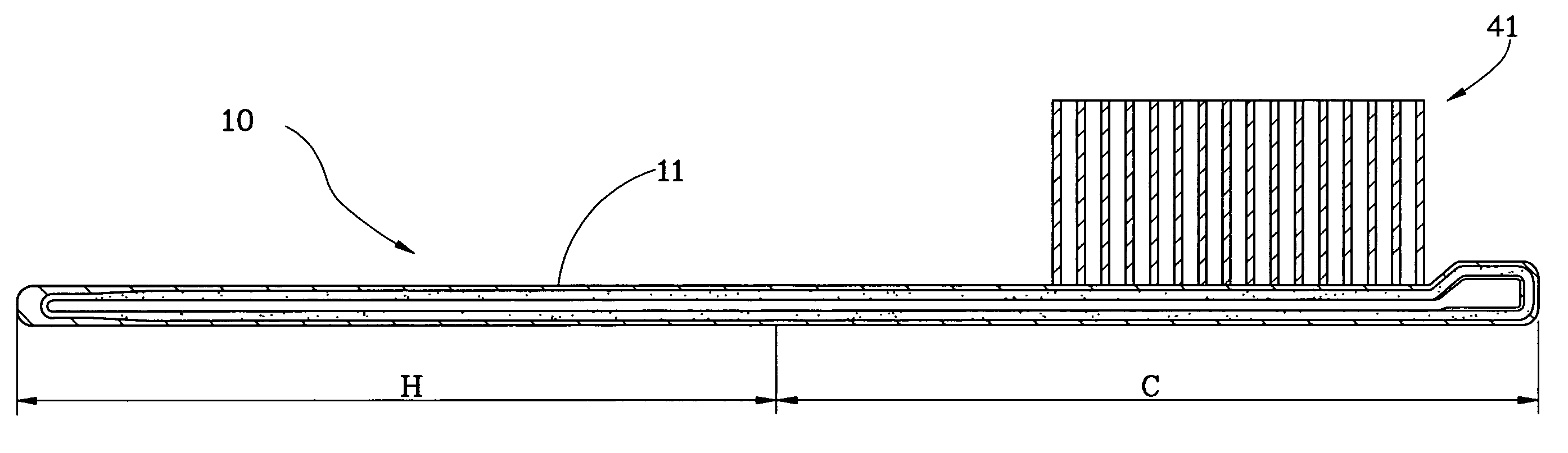
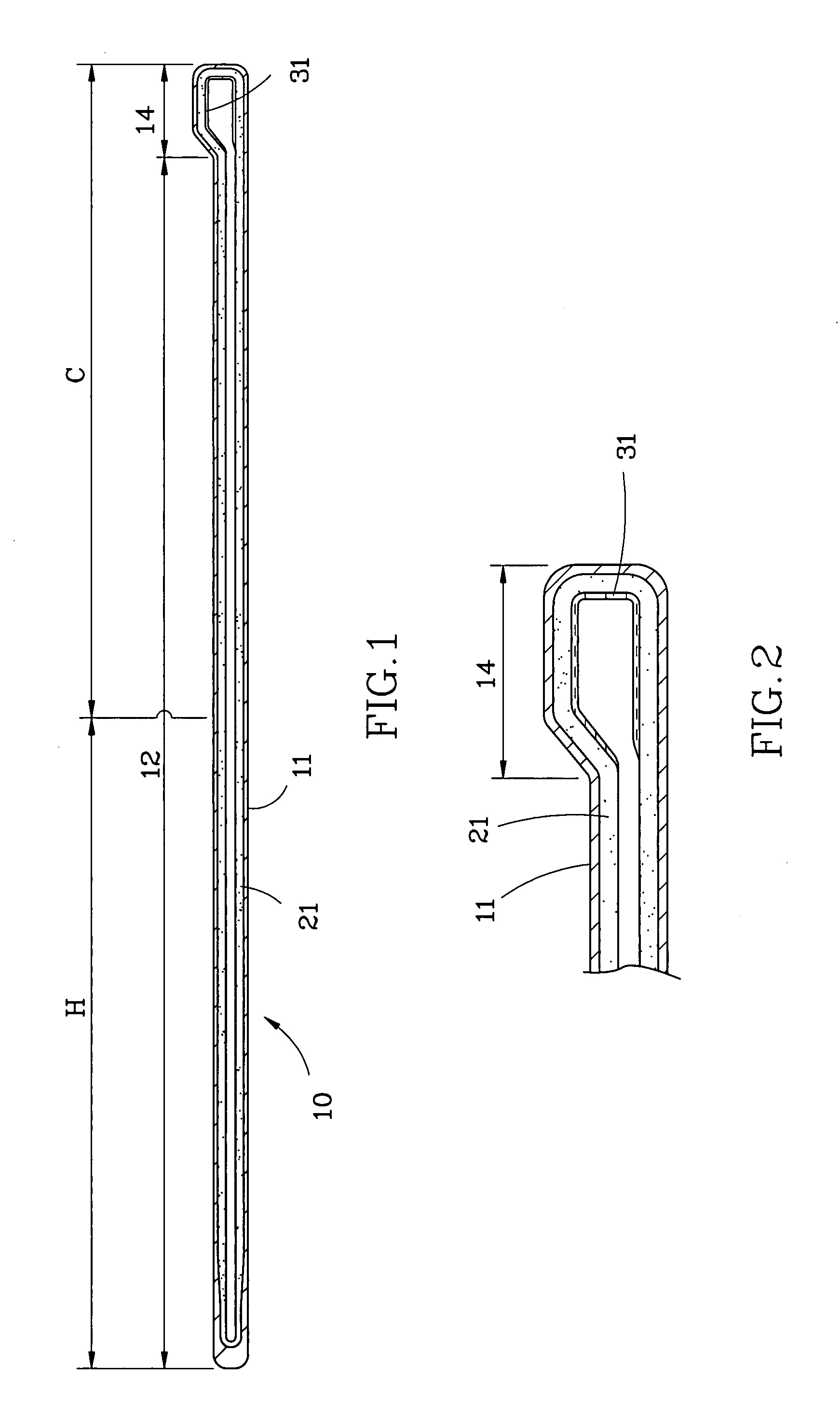
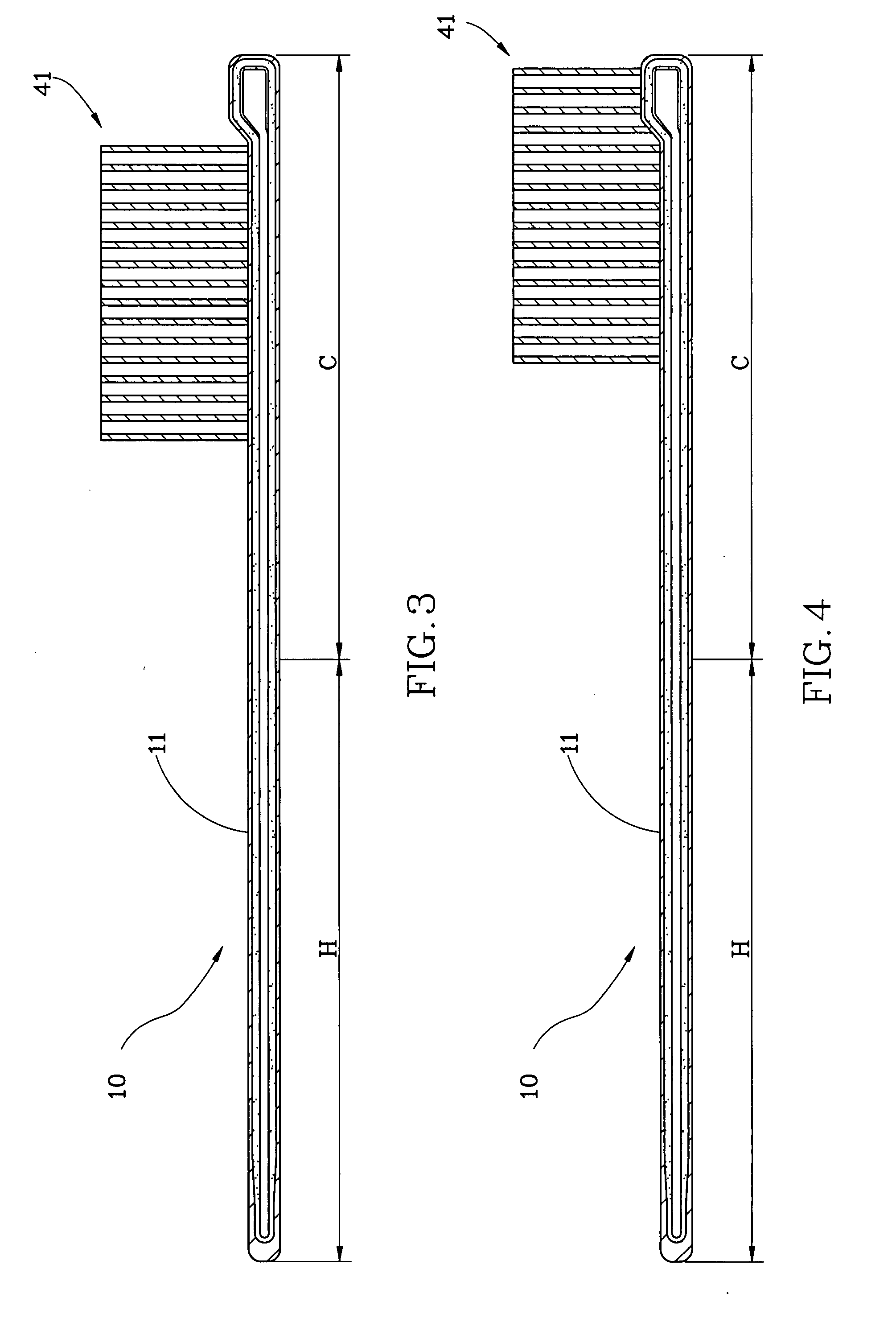
[0016]Referring to FIG. 1 and FIG. 2, the flat heat pipe 10 of present invention including: a tubular member 11, a capillary wick 21 and liquid 31. Wherein:

[0017]Said tubular member 11 makes of copper and both ends are sealed.

[0018]Said capillary wick 21 is disposed at the internal sidewall of said tubular member 11. Said capillary wick 21 can be a metal mesh or copper powder or grooves that is provided at the internal sidewall of said tubular member 11. In this embodiment, present invention takes the sintering by copper powder as an illustration. The metal mesh and the grooves type are all prior art skills and the capillary wick is not the technique key point of present invention, so there are no more redundancy words.

[0019]Said liquid 31 is disposed into said tubular member 11. Wherein said tubular member 11 defines a flat section 12 and a thicker section 14. Said flat section 12 is placed at one end of said tubular member 11 and said thicker section 14 is placed at the other end,...


PUM


Abstract

A flat heat pipe including: a tubular member having two sealed ends, a capillary wick being disposed at the internal sidewall of said tubular member and a liquid contained in said tubular member. Said tubular member defines a flat section and a thicker section at least. By the way, the present invention can solve the problem of the accumulated water inside the heat pipe of prior art and keeps a good efficiency of uniform temperature, and the radiation efficiency is better then the heat pipe of prior art.

Description

BACKGROUND OF THE INVENTION[0001]1. Field of the Invention[0002]The present invention relates to a heat-dissipating device and more particular to a flat heat pipe.[0003]2. Description of the Related Art[0004]A conventional heat pipe is usually composed of a sealed tubular member, a capillary wick mounted on the internal wall of the sealed tubular member, and adequate liquid, employing the liquid-vapor transformation and the flowage of the liquid for thermal conduction. In practical operation, water located at a heated section of the sealed tubular member is heated to be transformed into vapor, the vapor is then diffused to a condensed section of the sealed tubular member to be transformed into water, and then the water is returned to the heated section through the capillary action generated by the capillary wick, thus completing heat exchange. Such endless cycles of endothermic and exothermic reactions can effect rapid thermal conduction.[0005]However, in some device with limited sp...

Claims


Application Information

Patent Timeline
IPC IPC(8): F28D15/04
CPCF28D15/0233F28D15/046
Inventor LAI, YAW-HUEY
Owner TAI SOL ELECTRONICS
Why Eureka
Try Eureka