Organic light emitting display

a light-emitting display and organic technology, applied in the field of organic light-emitting displays, can solve the problems of reducing the reliability of the product, the operation cost of the module process for a defective panel having a short is additionally needed, and achieves the effect of reducing the module process cost and high reliability

Inactive Publication Date: 2008-10-09
SAMSUNG DISPLAY CO LTD
View PDF19 Cites 34 Cited by
  • Summary
  • Abstract
  • Description
  • Claims
  • Application Information

AI Technical Summary

Benefits of technology

[0037]As described above, according to the organic light emitting display of an exemplary embodiment of the present invention, such a desirable effect is attained that it is possible to reduce a module process cost by detecting longitudinal short defect of a pixel circuit of an organic light emitting display panel in advance and it is possible to have high reliability.

Problems solved by technology

However, a module process operation cost for a defective panel having a short is additionally needed.
When a total inspection is not performed during the module process, reliability of the product is lowered because a longitudinal short cannot be detected as a defect during manufacturing, such that the defect is discovered by the end user of the product.

Method used


Image

  • Organic light emitting display
  • Organic light emitting display
  • Organic light emitting display

Examples


Embodiment Construction

[0049]Hereinafter, exemplary embodiments of the present invention will be described in detail with reference to the accompanying drawings.

[0050]It should be understood that electrical coupling between a certain element and another element includes direct electrical coupling between them as well as indirect electrical coupling between them by an interposed element.

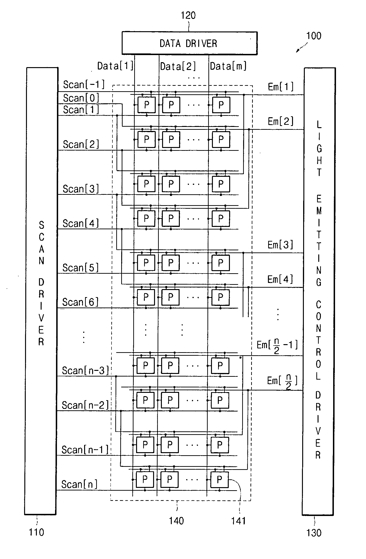
[0051]FIG. 1 illustrates a schematic block diagram of an organic light emitting display according to an exemplary embodiment of the present invention.

[0052]As illustrated in FIG. 1, an organic light emitting display 100 in one exemplary embodiment includes a scan driver 110, a data driver 120, a light emitting control driver 130 and an organic light emitting display panel 140 (hereinafter, referred to as a “panel”).

[0053]The scan driver 110 can sequentially supply scan signals to the panel 140 through a plurality of scan lines (Scan[1], Scan[2], . . . , and Scan[n]).

[0054]The data driver 120 can supply data signals to the p...


PUM


Abstract

An organic light emitting display includes: a first shift register which is electrically coupled with a clock line, a negative clock line, and an initial drive line; a first NAND gate which is electrically coupled with the initial drive line, a first light emitting control line which is an output line of the first shift register, and a first clock line; a second NAND gate which is electrically coupled with the initial drive line, the first light emitting control line, and a second clock line; a first pixel part which is electrically coupled with a first scan line which is an output line of the first NAND gate; a second pixel part which is electrically coupled with a second scan line which is an output line of the second NAND gate; a third pixel part which is electrically coupled with the first scan line; and a fourth pixel part which is electrically coupled with the second scan line.

Description

CROSS-REFERENCE TO RELATED APPLICATIONS[0001]This application claims priority to and the benefit of Korean Patent Application No. 10-2007-0034285, filed on Apr. 6, 2007, the entire content of which is incorporated herein by reference.BACKGROUND OF THE INVENTION[0002]1. Field of the Invention[0003]The present invention relates to an organic light emitting display.[0004]2. Description of the Prior Art[0005]An organic light emitting display is a display that emits light by electrically exciting a fluorescent or phosphorescent compound and can display an image by driving N×M organic light emitting diodes. The organic light emitting diode includes an anode (ITO), an organic thin-film, and a cathode (metal). The organic thin-film is formed in a multi-layer structure including a light emitting layer EML that emits light when electrons are coupled with holes, an electron transport layer ETL that transports electrons, and a hole transport layer HTL that transports holes. The organic thin-fil...

Claims


Application Information

Patent Timeline
Patent Type & Authority Applications(United States)
IPC IPC(8): G09G3/30
CPCG09G3/006G09G3/3233G09G3/3266G09G2300/0819G09G2300/0852G09G2300/0861G09G2310/0224G09G2310/0286G11C19/00G11C19/28H05B33/02
Inventor KIM, JONGYUN
Owner SAMSUNG DISPLAY CO LTD
Why Eureka
Try Eureka