Electooptical Communications and Power Cable

Inactive Publication Date: 2008-10-09
BRUGG KABEL
View PDF4 Cites 375 Cited by
  • Summary
  • Abstract
  • Description
  • Claims
  • Application Information

AI Technical Summary

Benefits of technology

[0029]The insulating layer is expediently made from a dielectric plastic, in particular polyethylene or polypropylene. The outer sheath can be made from the same materi

Problems solved by technology

Conventional steel tubes are not very suitable or not suitable at al

Method used


Image

  • Electooptical Communications and Power Cable
  • Electooptical Communications and Power Cable

Examples


example

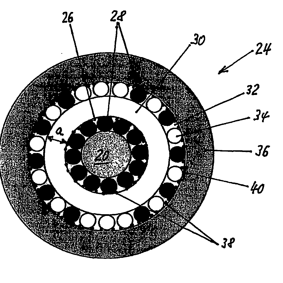
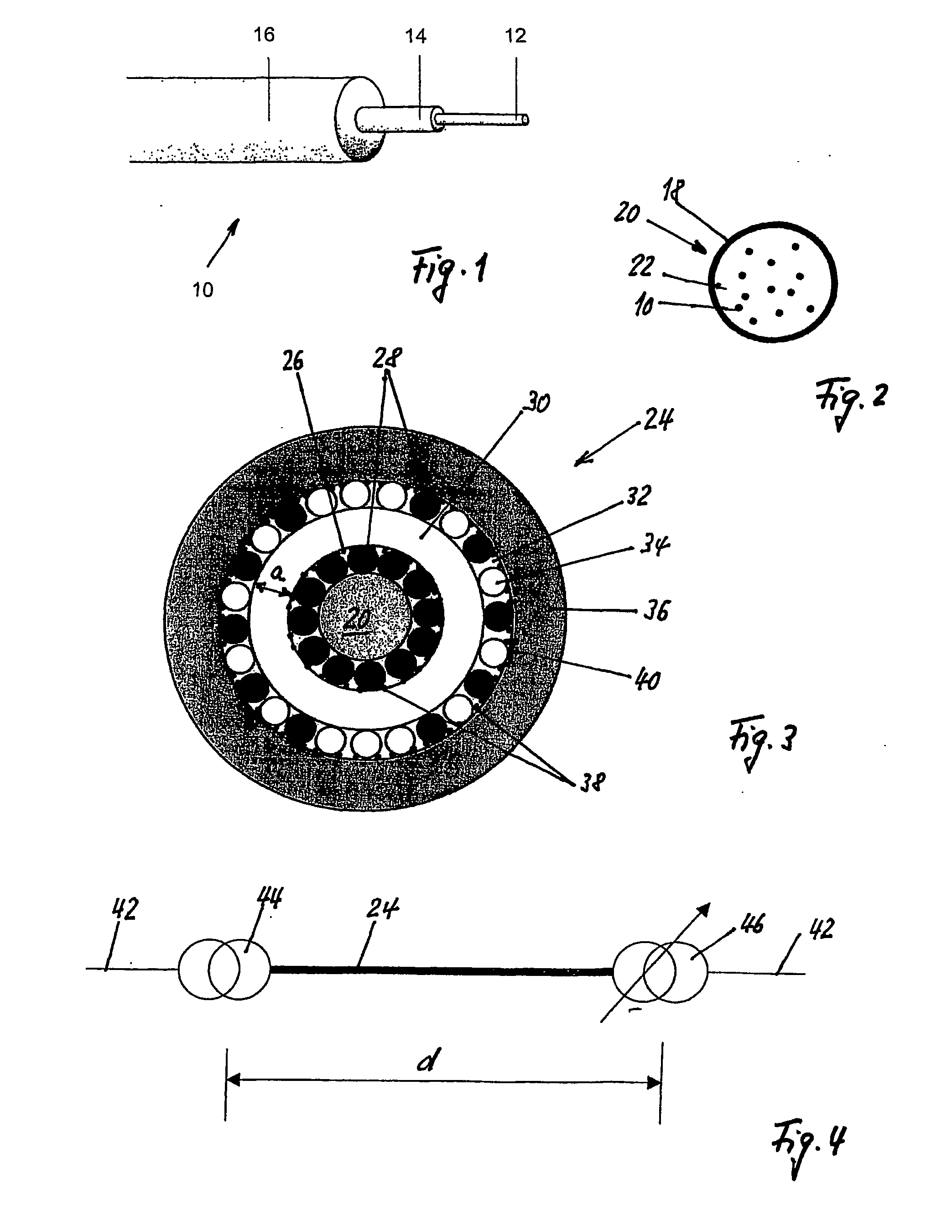
[0054]Electrooptical communications and power cable Electrically highly conductive copper wires 28 and stainless steel wires 34, with a diameter of 0.40 and 0.42 mm, respectively, are stranded in accordance with the invention. The arrangement in the communications and power cable corresponds to FIG. 3, in particular also the sequence of the copper wires 28 and stainless steel wires 34. These wires are separated from one another by means of a PE insulating layer 30 which is 0.6 mm thick (thickness a). The outer protection is ensured by an outer sheath 36 comprising a polyurethane layer which is 0.8 mm thick. The inner and the outer wire layer 26, 34 are covered by a Melinex strip. The communications and power cable 24 has an outer diameter of 5.8 mm, weighs 68 kg / m and has a total conductor cross section of the copper cables of approximately 1.5 mm2.

[0055]Electrical conductivity

δCu=0.0172(Ω.mm2) / m

δstainless steel=0.4129(Ω.mm2) / m.

[0056]Resistances per km and per wire

[0057]Cu wire: cro...


PUM


Abstract

An electrooptical communications and power cable has at least one light waveguide, which is arranged in a central multifibre bundle consisting of a smooth flexible metal tube and provided with a primary jacket. Two layers of stranded metal wires are extended coaxially to the multifibre bundle. The metal wires are also used for relieving a traction and/or transversal load. The internal metal wire layer consists of metal wires exhibiting a good electric conductivity. The external metal wire layer has metal wires which are arranged alternately individually and/or group groupwisely and exhibit a good electrical conductivity and metal wires exhibiting a high traction strength. The two wire layers are held at a distance (a) from each other by an insulating layer. The communications and power cable is used first of all for an electrooptical power connection between two voltage converters in an intelligent system.

Description

BACKGROUND[0001](1) Field of the Invention[0002]The invention relates to an electrooptical communications and power cable, which comprises, in a central bundle core comprising a smooth, flexible metal tube, at least one optical waveguide with a primary sheathing, two layers running coaxially with respect to the bundle core and comprising stranded metal wires, which are also used as relief from tensile and / or transverse forces, and an outer sheath. Furthermore, the invention relates to a use for the electrooptical communications and power cable.[0003](2) Prior Art[0004]Optical cables with optical waveguides, in particular optical fibers, have been known for many decades. The data are transmitted not in the form of electrical pulses through metal conductors but as light quanta in optical waveguides. Interfaces are electrooptical couplings, which convert electrical pulses into light quanta, and vice versa.[0005]Modern optical waveguides and optical communications and power cables with ...

Claims


Application Information

Patent Timeline
IPC IPC(8): H01B11/22
CPCG02B6/4416
Inventor THOMAS, RYTZRUTSCHI, MARTIN
Owner BRUGG KABEL
Why Eureka
Try Eureka