Unit and Method for Conveying Workpieces Along a Processing

US20080247847A1Inactive Publication Date: 2008-10-09DUERR SYST GMBH

Image

  • Unit and Method for Conveying Workpieces Along a Processing
  • Unit and Method for Conveying Workpieces Along a Processing
  • Unit and Method for Conveying Workpieces Along a Processing

Examples


Embodiment Construction

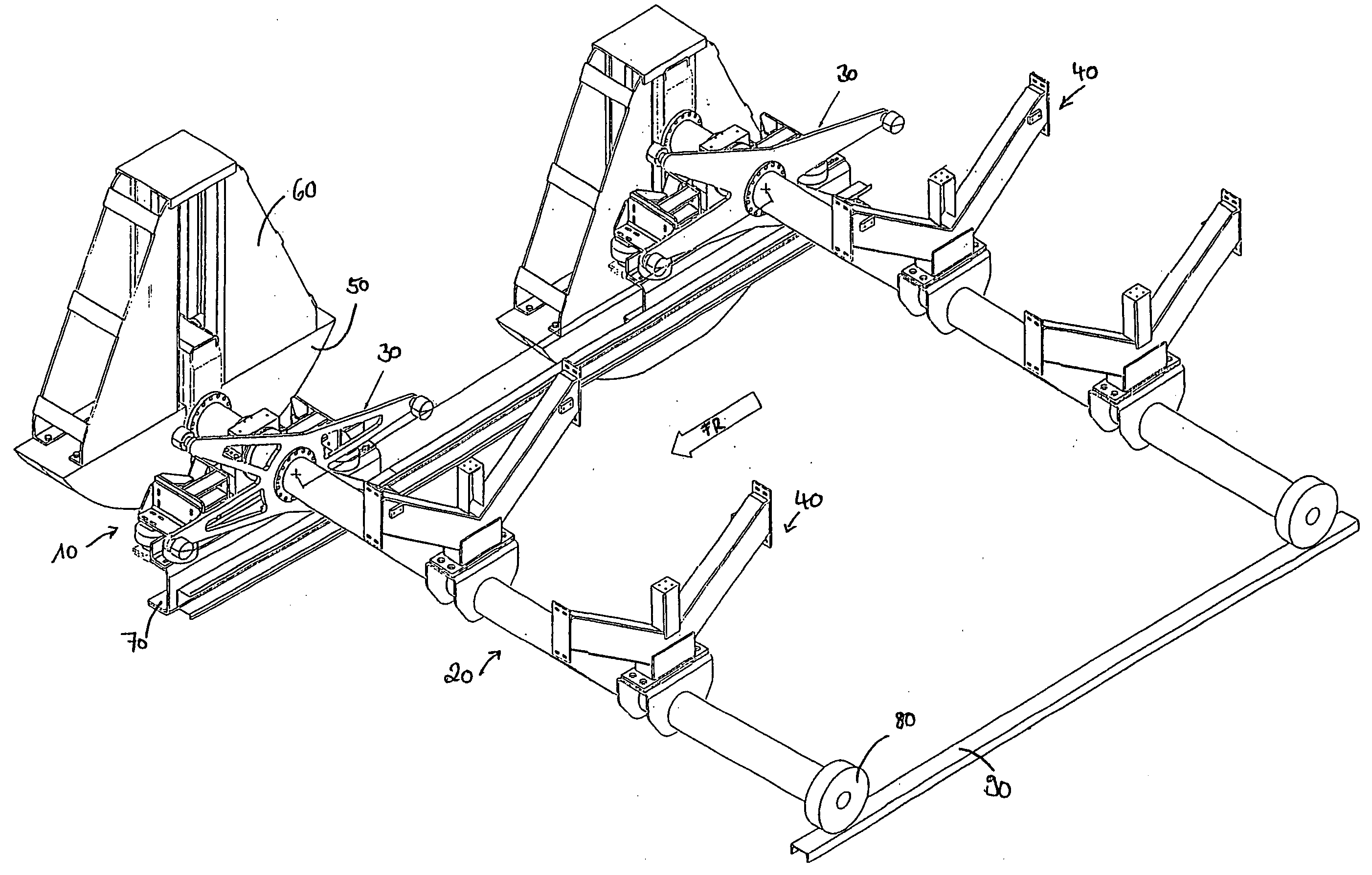
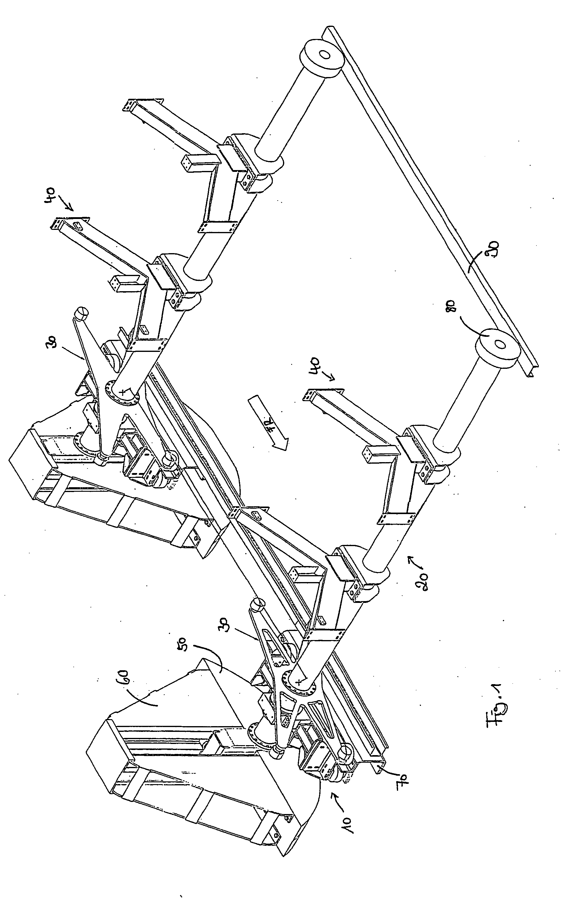
[0041]A schematic overall view of a unit according to the invention is shown in FIG. 1.

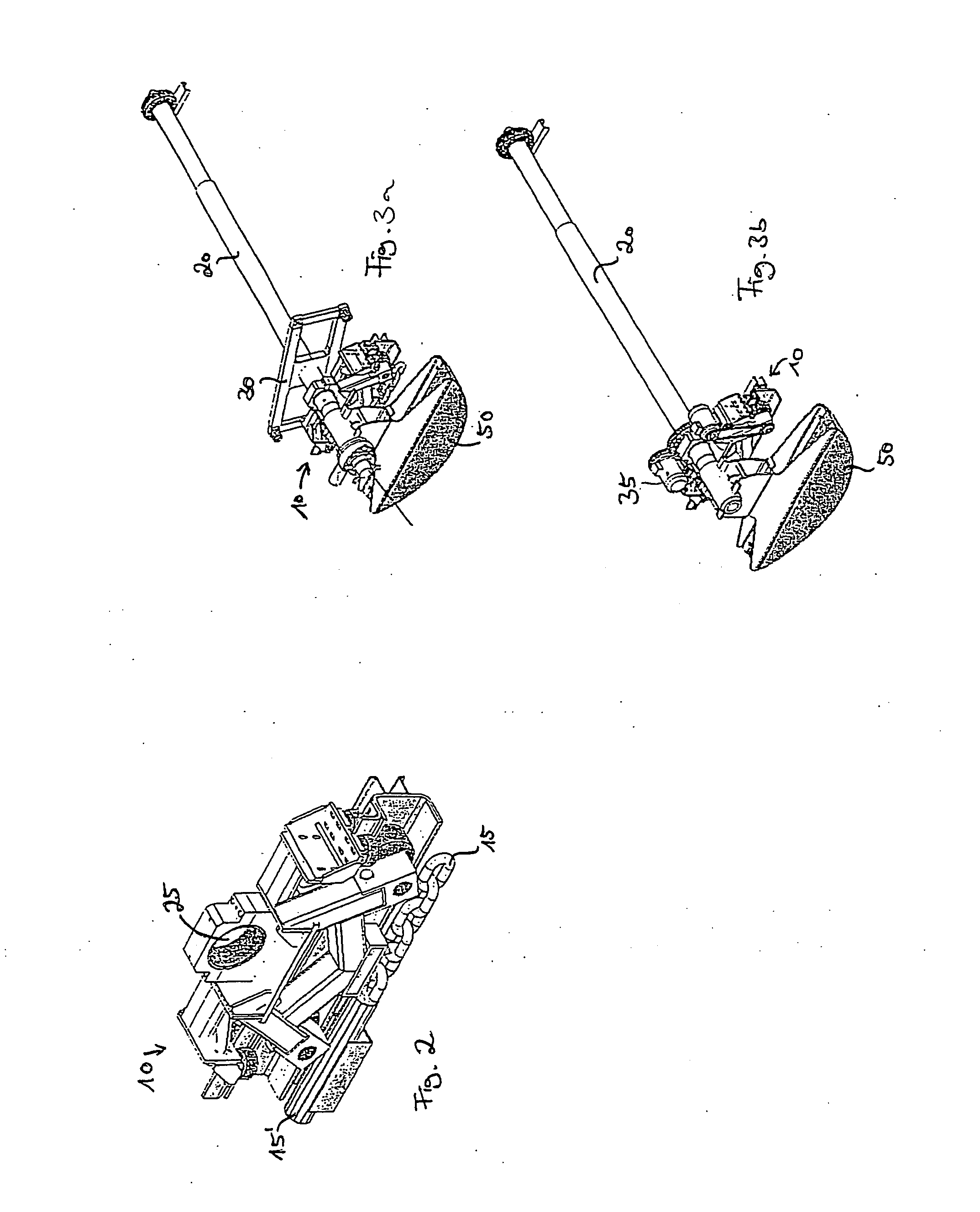
[0042]Using this unit, workpieces can be transported through a processing station. In particular, a unit of this type may serve to guide car body parts through a dipping bath in order to varnish the same. For this purpose, the unit comprises a plurality of tool carriers, two of which are shown in FIG. 1, and which are each formed by a transport car 10 and a rotating shaft 20 as essential parts.

[0043]Rotating shafts 20, in turn, each show mounts 40, on which the car body parts which are to be varnished can be fixed directly or using so-called skids. Rotating shafts 20 are rotatably supported on transport car 10 and move together with transport car 10 in a conveying direction characterized by “FR” along a guiding way 70. For this purpose, transport cars 10 are driven, for example using a conveying chain, a rope or a belt. A dipping bath (not shown), into which the car body parts which are fixed to m...


PUM


Abstract

A unit and method are provided for conveying workpieces along a processing run, having at least one transport car (10), moving along the processing run in a conveying direction (FR) and a rotating shaft (20), mounted on the transport car (10), close to a first of the ends thereof, to rotate about the axis thereof at right angles to the conveying direction (FR) and on which a mounting (40) for the workpiece to be processed is provided. The rotating shaft (20) is only mounted close to the first end thereof on the transport car (10) and may thus be driven in the conveying direction (FR), the second free end thereof being passively transported along in the conveying direction (FR). It is thus possible to pivot the rotating shaft (20) in a plane running at right angles to the conveying direction, in particular, to permit a space saving return.

Description

TECHNICAL FIELD[0001]The invention relates to a unit for conveying workpieces on a processing run.[0002]Along such a processing run, there is located at least one, however, mostly several of successive processing stations into which said workpieces are introduced for surface treatment.[0003]Such a processing station may, for example, be a dipping bath containing a processing liquid, the expression processing station may, however, also be understood to be any other kind of cabin or basin in which processing of the workpiece takes place. Such treatment may, for example, also encompass a washing process. Other examples of processing are dipping-phosphatizing, pre-treatment for immersion-painting, powder-coating, wet-painting or the like.PRIOR ART[0004]Units known so far for the surface treatment of workpieces, such as car bodies in dipping baths or processing cabins, are divided into continuously conveying units and non-continuously conveying units.[0005]In continuously conveying units...

Claims


Application Information

Patent Timeline
09 Oct 2008
Publication
US20080247847A1
IPC
B65H1/00; B65G49/04
CPC
B65G49/0459; B65G49/0463; B65G2812/02128; B65G2812/02326
Inventors
MULLER, HERBERT; WINKLER, JURGEN