Liquid developing agent, method of producing the same and method of producing display device

Inactive Publication Date: 2008-10-09
KK TOSHIBA
View PDF1 Cites 47 Cited by
  • Summary
  • Abstract
  • Description
  • Claims
  • Application Information

AI Technical Summary

Benefits of technology

[0015]The present invention has been made in view of such a problem, and it is an object thereof to provide a liquid developing agent

Problems solved by technology

However, while these technologies are more and more improved in resolution and performance, they require a huge and expensive production facility, with the production cost rising with the resolution.
However, the photolithographic technologies described above can no longer meet such needs.
However, there are limitations to improvements in resolution and productivity.
Therefore, not only must a volatile organic solvent other than an insulation solvent be used but also a resin having a controlled SP value must be designed, which therefore makes it difficult to control the intrinsic characteristics of the toner such as charging ability, adhesiveness and coagulation ability, which strictly limits the range of material selectable.
When, for example, th

Method used


Image

  • Liquid developing agent, method of producing the same and method of producing display device
  • Liquid developing agent, method of producing the same and method of producing display device
  • Liquid developing agent, method of producing the same and method of producing display device

Examples


Example

Example 1

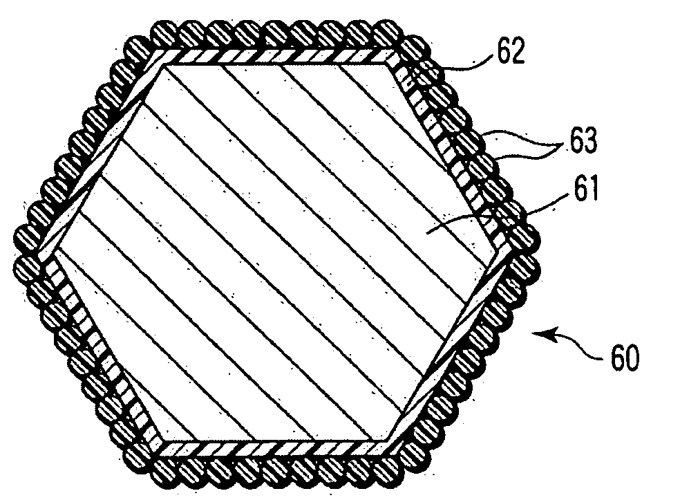
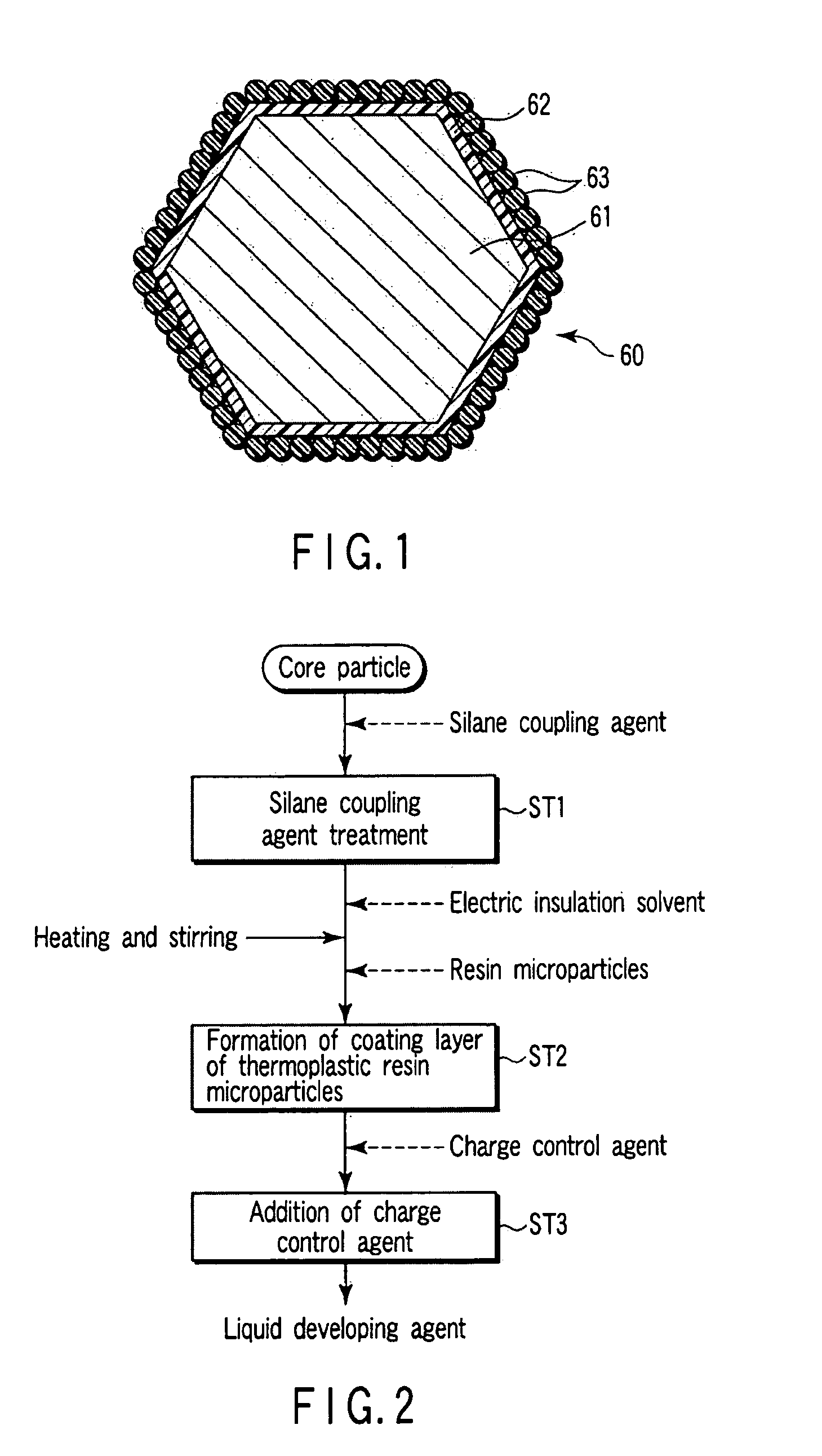
[0218]700 g of an aqueous solution of a silane coupling agent (KBM-603, manufactured by Shin-Etsu Chemical Co., Ltd.) was prepared in a 1000 ml beaker, into which 50 g of Y2O2S:Eu type red emission fluorescent body particles (average particle diameter: 4.5 μm, specific gravity: 5.0) was poured and stirred for 2 hours. Then, the reaction mixture was filtered and dried at 120° C. for 3 hours in a drying furnace to carry out silane coupling treatment, followed by screening. Next, 180 g of an insulation hydrocarbon solvent (Isoper L, manufactured by Exxon Kagaku) having a boiling point range of 191 to 205° C. was poured into a 500 ml separable flask and next, 2 g of acryl microparticles (MP4009, manufactured by Soken Chemical & Engineering Co., Ltd.) having a specific gravity of 1.0 and 18 g of Y2O2S:Eu type red emission fluorescent body particles which had been subjected to silane coupling treatment were poured into the flask. Then, the relay temperature regulating unit used a...

Example

Example 2

[0225]700 g of an aqueous solution of a silane coupling agent (KBM-603, manufactured by Shin-Etsu Chemical Co., Ltd.) was prepared in a 1000 ml beaker, into which 50 g of ZnS:Cu, Al type green emission fluorescent body particles (average particle diameter: 5.6 μm, specific gravity: 4.1) was poured and stirred for 2 hours. Then, the reaction mixture was filtered and dried at 120° C. for 3 hours in a drying furnace, followed by screening. Next, 180 g of an insulation hydrocarbon solvent (Isoper L, manufactured by Exxon Kagaku) having a boiling point range of 191 to 205° C. was poured into a 500 ml separable flask and next, 2 g of acryl microparticles (MP4009, manufactured by Soken Chemical & Engineering Co., Ltd.) having a specific gravity of 1.0 and 18 g of ZnS:Cu, Al type green emission fluorescent body particles which had been subjected to silane coupling treatment were poured into the separable flask. Then, the relay temperature regulating unit used as the temperature con...

Example

Example 3

[0229]700 g of an aqueous solution of a silane coupling agent (KBM-603, manufactured by Shin-Etsu Chemical Co., Ltd.) was prepared in a 1000 ml beaker, into which 50 g of ZnS:Ag, Al type blue emission fluorescent body particles (average particle diameter: 5.6 μm, specific gravity: 4.1) was poured and stirred for 2 hours. Then, the reaction mixture was filtered and dried at 120° C. for 3 hours in a drying furnace, followed by screening. Next, 180 g of an insulation hydrocarbon solvent (Isoper L, manufactured by Exxon Kagaku) having a boiling point range of 191 to 205° C. was poured into a 500 ml separable flask and next, 2 g of acryl microparticles (MP4009, manufactured by Soken Chemical & Engineering Co., Ltd.) having a specific gravity of 1.0 and 18 g of ZnS:Ag, Al type blue emission fluorescent body particles were poured into the flask. Then, the relay temperature regulating unit used as the temperature controller was set to 100° C. and the mixture was stirred by the stir...


PUM


Abstract

On the surface of a core particle of a toner particle, a silane coupling agent treatment layer, a coating layer of thermoplastic resin microparticles applied to the core particle and a charge control agent added to the coating layer through the silane coupling agent treatment layer are provided, wherein the toner particle has a particle diameter of 1 to 10 μm, or on the surface of a core particle of a toner particle, a coating layer of thermoplastic resin microparticles and a charge control agent added to the coating layer and made of an organic compound containing at least one type of lanthanoid metal are provided, or on a ZnS type fluorescent body core particle, a coating layer of thermoplastic resin microparticles and a charge control agent added to the coating layer and including a metal compound containing the IIA metal or IIIA group metal are provided.

Description

CROSS REFERENCE TO RELATED APPLICATIONS[0001]This is a Continuation Application of PCT Application No. PCT / JP2007 / 068866, filed Sep. 27, 2007, which was published under PCT Article 21(2) in Japanese.[0002]This application is based upon and claims the benefit of priority from prior Japanese Patent Applications No. 2006-269402, filed Sep. 29, 2006; No. 2007-082781, filed Mar. 27, 2007; and No. 2007-085717, filed Mar. 28, 2007, the entire contents of all of which are incorporated herein by reference.BACKGROUND OF THE INVENTION[0003]1. Field of the Invention[0004]The present invention relates to a method of producing a display device such as a plasma display and field emission display, a liquid developing agent used in these displays and a method of producing the liquid developing agent.[0005]2. Description of the Related Art[0006]Photolithographic technologies have played a central role as technologies for forming fine patterns on the surface of a base material. However, while these te...

Claims


Application Information

Patent Timeline
IPC IPC(8): G03G9/08G03G13/04
CPCG03G9/0819G03G9/0825G03G9/122G03G9/13G03G9/1355
Inventor ISHII, KEITASHINJO, YASUSHITAKEMURA, HIROFUMIAOKI, KATSUYUKI
Owner KK TOSHIBA
Why Eureka
Try Eureka