Device For Carrying Out A Biological Assay

a technology for biological assays and devices, applied in laboratory glassware, instruments, paper/cardboard containers, etc., to achieve the effects of reducing the cost of mass production, great flexibility of design freedom, and improving the chemical resistance against acids and bases

Inactive Publication Date: 2008-10-09
NORCHIP AS
View PDF10 Cites 76 Cited by
  • Summary
  • Abstract
  • Description
  • Claims
  • Application Information

AI Technical Summary

Benefits of technology

[0018]The reagent reservoir systems are preferably separate, meaning that they are not in direct fluid communication with each other. This provides an advantage in parallel detection of, multiple different target molecules, since it minimises the possibility of cross-contamination between the detection assays carried out at each reaction site. Should it be necessary, fluid flow from a reagent reservoir to the reaction site in fluid communication therewith may be controlled by the optional inclusion of a valve.
[0036]When such ELISA-type binding assays are performed in the device of the invention the reaction sites of the device may provide the solid support on which the assay takes place.
[0039]The capture receptors are preferably fixed or retained in the reaction site throughout the duration of the assay. The capture receptors may be immobilised in the reaction site, for example by covalent linkage or non-specific adsorption to an interior surface of the reaction site. This ensures that the capture receptors remain located within the reaction site during all sample and reagent addition steps, effectively confining the assay to the reaction site. This arrangement opens up the possibility of using assay formats wherein the signal providing the final read-out of the assay is generated in free solution (e.g. the IMRAMP assay, real-time immuno-PCR etc.), and more particularly allows multiple assays based on such read-outs to be carried out in parallel within the device. Such assays can be carried out in parallel if the signal—generating steps of each individual assay, and preferably all steps of the assay, are contained and kept separate within or at separate reaction sites not in direct fluid communication with each other, such as is the case using the device of the invention.
[0049]The advantages of using plastics instead of silicon-glass for miniaturized structures are many, at least for biological applications. One of the greatest benefits is the reduction in cost for mass production using methods like microinjection moulding, hot embossing and casting. A factor of a 100 or more is not unlikely for complex structures. The possibility to replicate structures for multilayered mould inserts gives a great flexibility of design freedom. Interconnection between the micro and macro world are in many cases easier because one has the option to combine standard parts normally used. Different approaches can be used for assembly techniques, like e.g. US-welding with support of microstructures, laser welding, gluing and lamination. Surface modification may also be included. For miniaturized structures addressed for biological analysis, it is important that the surface is biocompatible. By utilizing plasma treatment and plasma polymerization a flexibility and variation of assortment can be adapted into the coating. Chemical resistance against acids and bases are much better for plastics than for silicon substrates that are easily etched away. Most detection methods within the biotechnological field involve optical measurements. The transparency of plastic is therefore a major feature compared to silicon that is not transparent. Polymer microfluidic technology is now an established yet growing field within the Lab-on-a-chip market.

Problems solved by technology

A difficulty faced in transferring such assays to a contained assay system, such as a lab-on-a-chip device, is in providing means for achieving this sequential addition of reagents in a pre-determined order.

Method used


Image

  • Device For Carrying Out A Biological Assay
  • Device For Carrying Out A Biological Assay
  • Device For Carrying Out A Biological Assay

Examples


Embodiment Construction

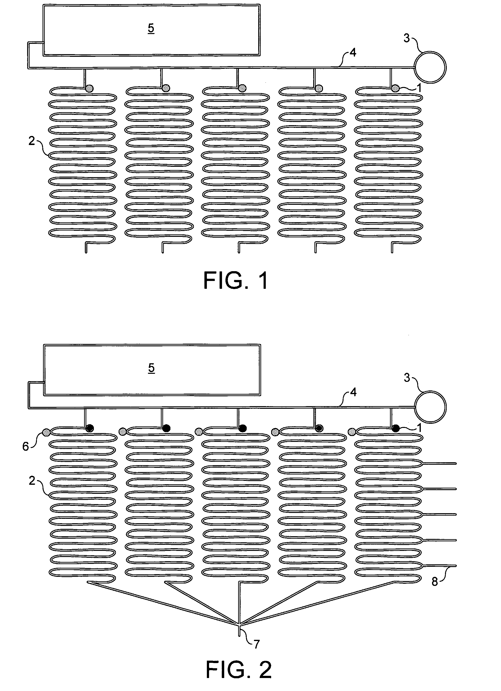
[0071]Referring to the drawings, FIG. 1 shows a device according to the invention comprising several reaction sites 1 each in fluid communication with a separate reagent reservoir system 2. The sample to be tested is applied at the inlet hole 3 and is communicated to each of the reaction sites via a supply channel 4. In this embodiment the reagent reservoir systems are formed of sinuate channels. The supply channel is in fluid communication with a waste chamber 5.

[0072]FIG. 2 shows an alternative device according to the invention. This embodiment is substantially similar to the device illustrated in FIG. 1 but further includes valves 6 located between each of the reaction sites and the reagent reservoir in fluid communication therewith. The valves will be opened for air when the sample is loaded. The sample will then fill the reaction sites until it reaches the valve. The valves are then closed. The rest of the sample will be drained into the waste unit or chamber 5. If required, su...


PUM

PropertyMeasurementUnit
thicknessaaaaaaaaaa
thicknessaaaaaaaaaa
volumeaaaaaaaaaa

Abstract

An integrated lab-on-a-chip device for carrying out an assay to detect the presence of a biological molecule in a fluid sample, the device comprising: (a) an inlet for a fluid sample; (b) one or more reaction sites each in fluid communication with the inlet; (c) one or more reagent reservoir systems each containing reagents required for an assay to detect a biological molecule, the reagents being arranged sequentially in each reservoir system in the order in which they are required for the assay and separated from one another by a fluid.

Description

FIELD OF THE INVENTION[0001]The invention is concerned with specific detection of biological molecules and, in particular, a lab-on-a-chip device for carrying out an assay to detect the presence of a biological molecule in a sample.BACKGROUND TO THE INVENTION[0002]There is considerable interest in the development of simplified assay systems for detection of biological molecules which allow an unskilled user to perform complex assay procedures without undue error. Moreover, there is a great deal of interest in the development of contained assay systems which require minimal handling of liquid reagents and which can be automated to allow the assay procedure to be performed with minimal intervention from the user, and preferably also miniaturized to provide a convenient system for point-of-care testing. This is particularly relevant in the healthcare field, especially diagnostics, where there is an increasing need for biological assay systems which can be efficiently and safely operate...

Claims


Application Information

Patent Timeline
Patent Type & Authority Applications(United States)
IPC IPC(8): G01N33/543B01J19/00B29C65/00C12M1/00B01L3/00
CPCB01L3/502784B01L2200/0621B01L2200/0673B01L2200/16Y10T156/10B01L2300/087B01L2400/0427B01L2400/0487B01L2300/0816
Inventor GULLIKSEN, ANJASOLLI, LARS ANDERSKARLSEN, FRANK
Owner NORCHIP AS
Why Eureka
Try Eureka