System and method for providing even heat distribution and cooling return pads

Inactive Publication Date: 2008-10-09
TYCO HEALTHCARE GRP LP
View PDF99 Cites 66 Cited by
  • Summary
  • Abstract
  • Description
  • Claims
  • Application Information

AI Technical Summary

Benefits of technology

[0013]The external power supply may be operable to limit the energy supplied to the at least o

Problems solved by technology

One issue with these adhesive electrodes was that current flow from the active electrode concentrates at the leading edge, the edge of the return pad closest to the active electrode, causing a heating imbalance across the return pad.
This phenomenon, known as “Leading Edge Effect” can cause tissue change or

Method used


Image

  • System and method for providing even heat distribution and cooling return pads
  • System and method for providing even heat distribution and cooling return pads
  • System and method for providing even heat distribution and cooling return pads

Examples


Embodiment Construction

[0035]Embodiments of the presently-disclosed electrosurgical return electrode (return pad) and method of using the same are described below with reference to the accompanying drawing figures wherein like reference numerals identify similar or identical elements. In the following description, well-known functions or constructions are not described in detail to avoid obscuring the disclosure in unnecessary detail. In addition, terms such as “above”, “below”, “forward”, “rearward”, etc. refer to the orientation of the figures or the direction of components and are simply used for convenience of description.

[0036]Heat Distribution

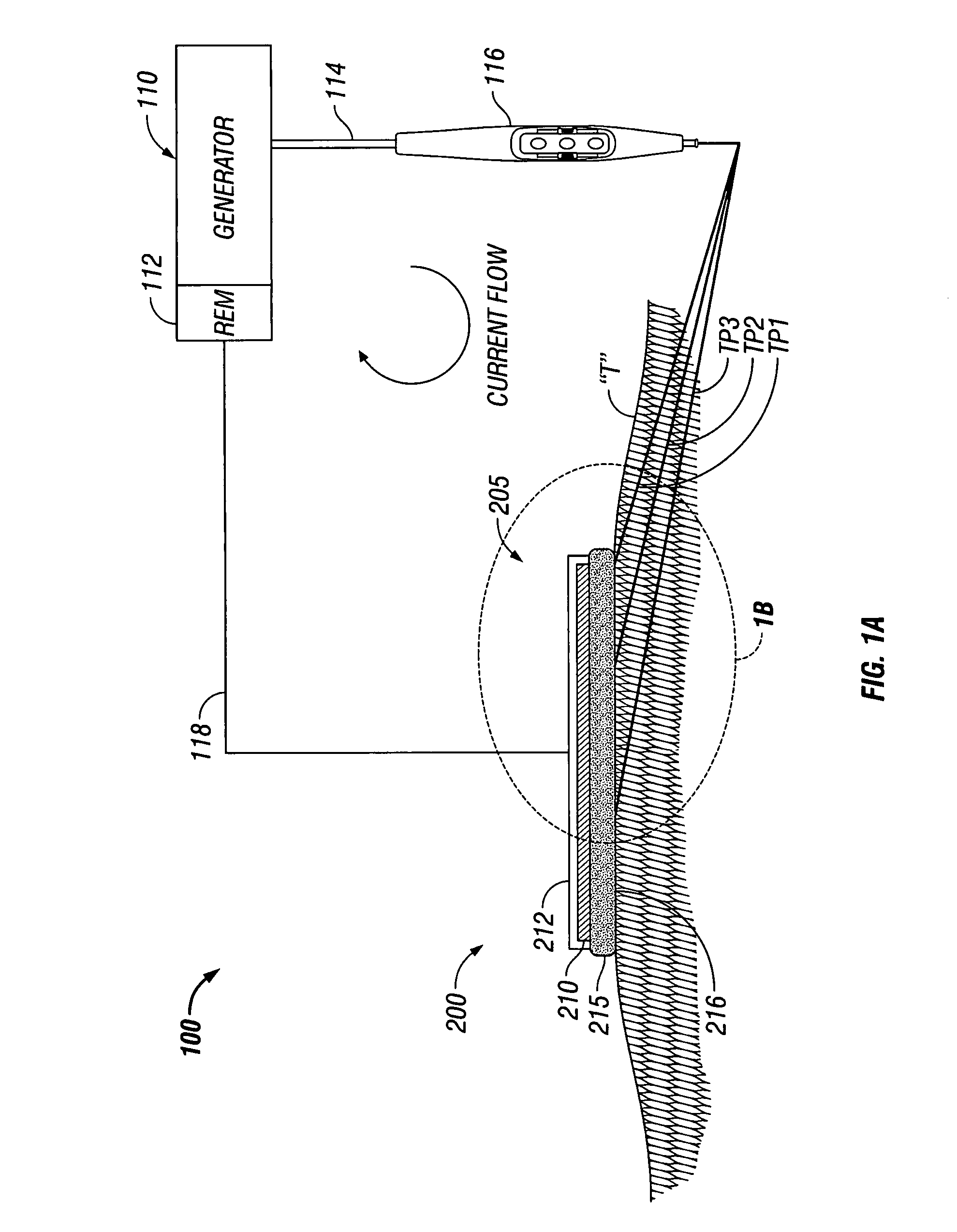
[0037]Referring initially to FIG. 1A, a schematic illustration of a monopolar electrosurgical system 100 is shown. The electrosurgical system 100 generally includes a return pad 200, an electrosurgical generator 110, a surgical instrument 116 (e.g., an active electrode) and a return electrode monitor (REM) 112. In FIG. 1A and in the figures hereinbelow, return ...


PUM


Abstract

The present disclosure relates to a return pad for use with an electrosurgical system and includes a contact layer configured to engage patient skin, a conductive layer disposed on the contact layer, and a heating layer operatively associated with at least one of the contact layer and the conductive layer. The heating layer is configured to heat the return pad.

Description

BACKGROUND[0001]1. Technical Field[0002]The present disclosure is directed to electrosurgical apparatus, methods and systems, and, in particular, to an electrosurgical return pad that provides even heat and current distribution and cooling.[0003]2. Background of Related Art[0004]During monopolar electrosurgery, a source or active electrode delivers energy, such as radio frequency energy, from an electrosurgical generator to the patient and a return pad carries the current back to the electrosurgical generator. The source electrode is typically placed at the surgical site and high density current flows from the source electrode to create the desired surgical effect of cutting and / or coagulating tissue. In tissue ablation, another form of electrosurgery, the source electrode or electrodes are typically placed in or adjacent the target tissue and high density current flows through the target tissue thereby destroying the target tissue. The patient return pad is placed at a distance fro...

Claims


Application Information

Patent Timeline
IPC IPC(8): A61B18/12
CPCA61B18/1233A61B18/16A61B2017/00084A61B2018/00005A61F7/007A61F2007/0056
Inventor DUNNING, JAMES E.
Owner TYCO HEALTHCARE GRP LP
Why Eureka
Try Eureka