Commercial Aircraft With a Main Deck and a Lower Deck

a commercial aircraft and lower deck technology, applied in the field of commercial aircraft, can solve the problem of larger cargo space on the main deck

Inactive Publication Date: 2008-10-16
AIRBUS OPERATIONS GMBH
View PDF14 Cites 20 Cited by
  • Summary
  • Abstract
  • Description
  • Claims
  • Application Information

AI Technical Summary

Benefits of technology

[0005]It is an objective of the present invention to propose a safe lower deck passenger cabin of the greatest length possible for a commercial aircraft with a fuselage diameter on the order of a wide-body aircraft and a main deck designed for use by passengers.

Problems solved by technology

One particular problem arises when—for example, in modem wide-body aircraft—the cargo space underneath the main deck is larger than necessary for transporting the luggage of the passengers.

Method used


Image

  • Commercial Aircraft With a Main Deck and a Lower Deck
  • Commercial Aircraft With a Main Deck and a Lower Deck
  • Commercial Aircraft With a Main Deck and a Lower Deck

Examples


Embodiment Construction

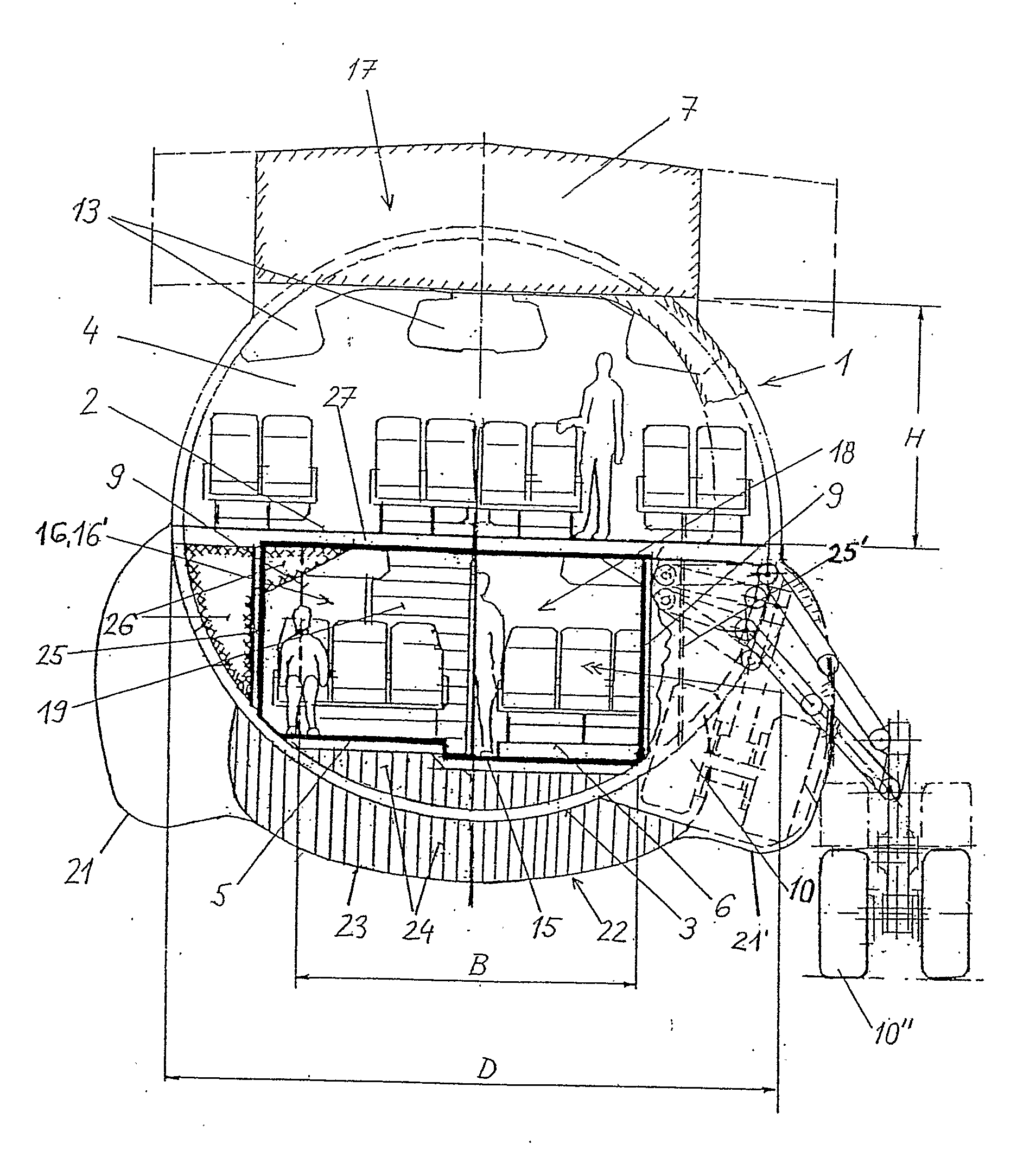
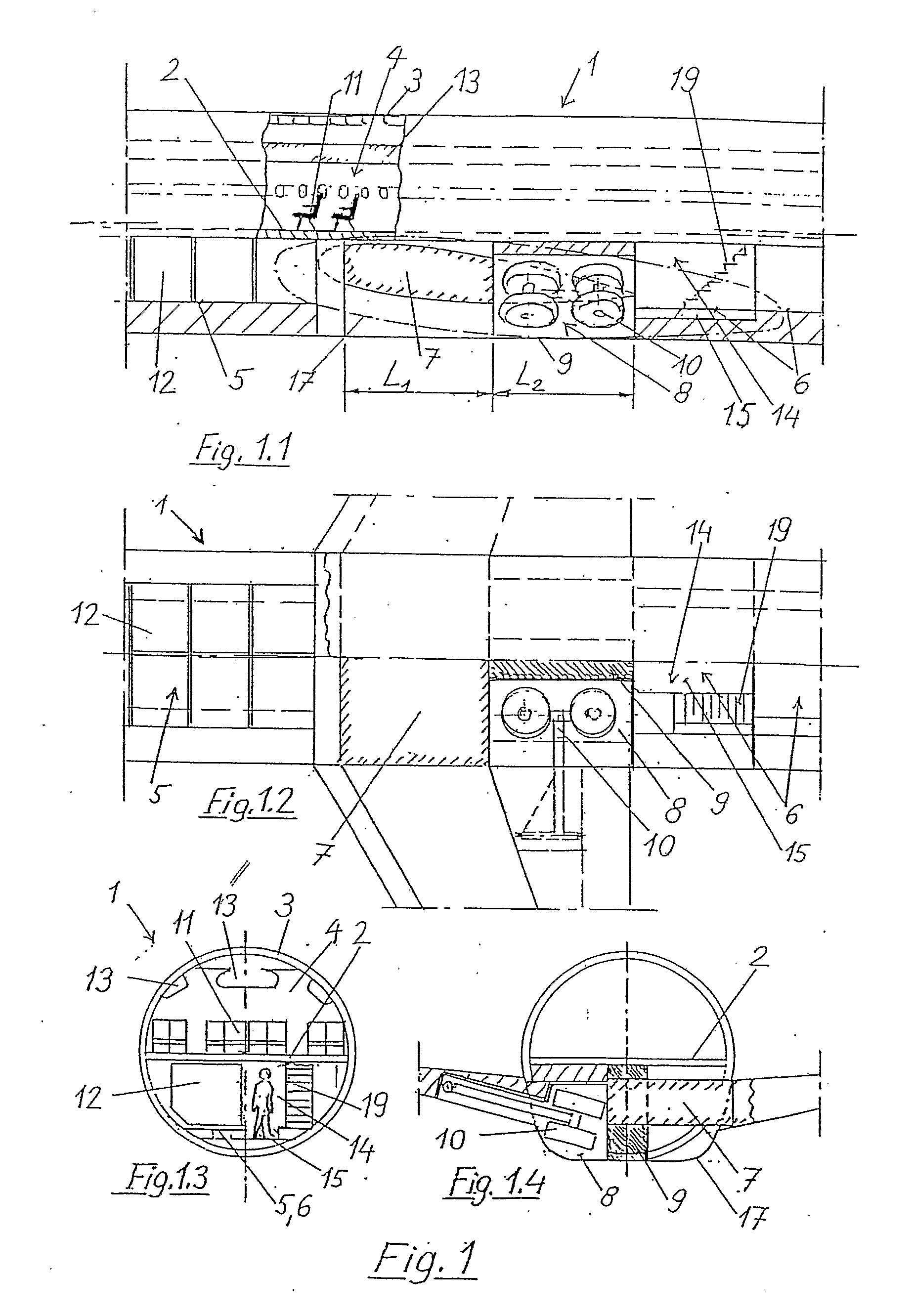
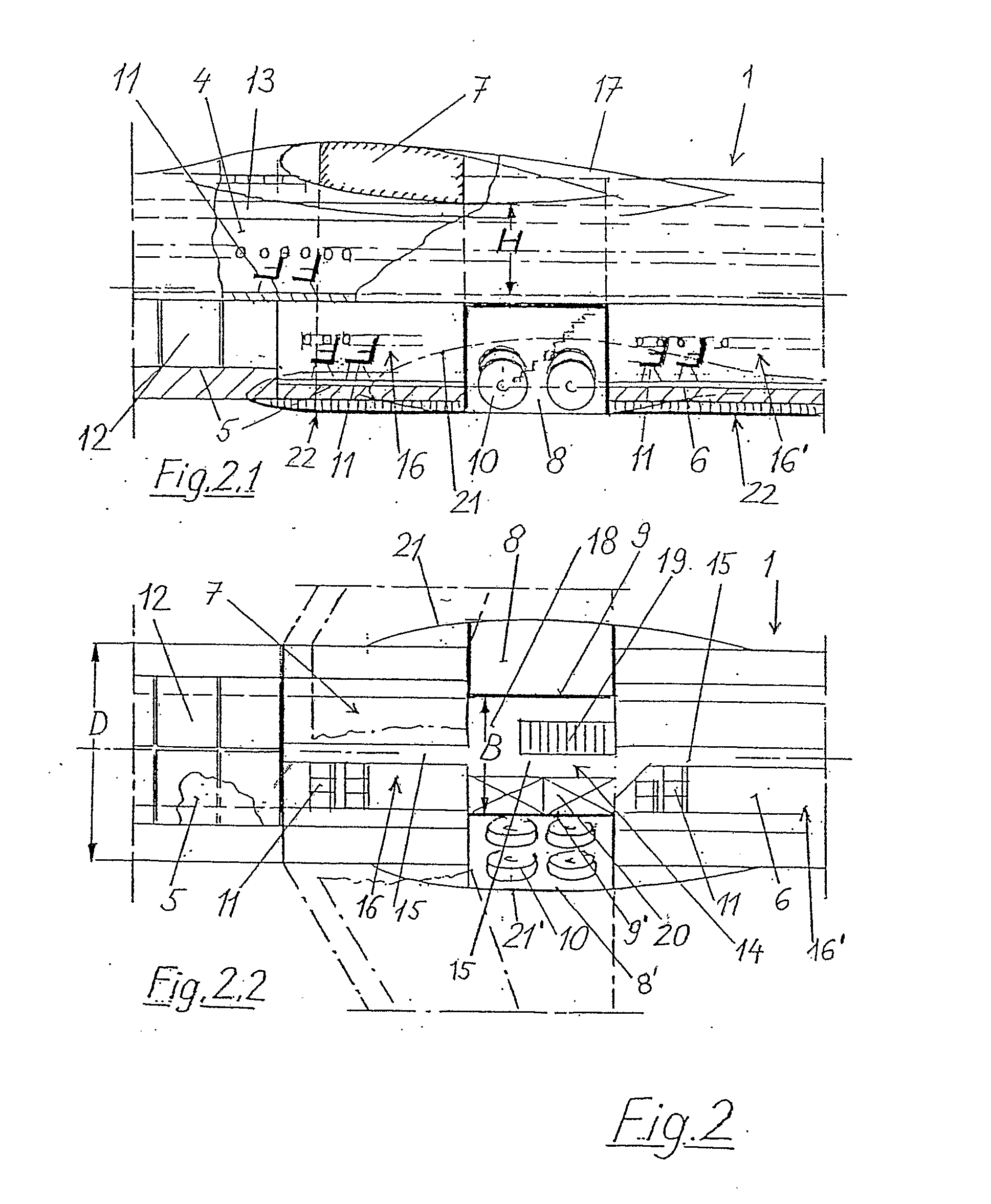
[0016]FIG. 1 shows a conventional low-wing wide-body aircraft in the form of horizontal and vertical sections (FIGS. 1.1 and 1.2), as well as cross sections through the fuselage (FIGS. 1.3 and 1.4). A main passenger cabin 4 is essentially formed by the main deck 2 and the upper fuselage shell 3. A front lower deck 5 and a rear lower deck 6, as well as a wing torsion box centerpiece 7 and the landing gear bays 8, are situated underneath the main deck 2. A bottom longeron spar 9 lying between these landing gear bays reinforces the fuselage 1 weakened by the cutouts for the large landing gear bays 8. The bottom longeron spars 9 and the landing gears 10 require so much space that the rear lower deck 6 cannot be extended forward in this region. In practical applications, the length L1 of the lower deck required for the wing centerpiece 7 and the length L2 occupied by the landing gear bays 8 add up to a considerable total length. Since this section of the lower deck cannot be used for pay...


PUM


Abstract

In a commercial aircraft with a main deck (2) and a lower deck (5, 6), at least one passenger cabin (16, 16′) is also provided on the lower deck. The fuselage diameter lies on the order of a wide-body aircraft, and an energy-absorbing deformation structure (22, 23, 24) is arranged underneath the lower deck cabin. The invention proposes to arrange the wings (7) on the aircraft fuselage in accordance with the shoulder wing configuration, and to arrange the landing gear (10) outside on the fuselage such that the landing gear bays are spaced apart from one another by a certain distance that is defined by the positioning of the bottom longeron spars (9). This may provide that the lower deck volume situated underneath the main deck can be optimally utilized for payloads. The lower deck areas may also be interconnected in such a way that a significant useful width of the passage between the landing gear bays is achieved.

Description

FIELD OF THE INVENTION[0001]The present invention relates to commercial aircraft. In particular, the present invention relates to a commercial aircraft with a main deck, a lower deck and a fuselage diameter on the order of a wide-body aircraft, wherein at least one passenger cabin is provided on the lower deck, and wherein an energy-absorbing deformation structure is arranged underneath the lower deck cabin.TECHNOLOGICAL BACKGROUND[0002]With respect to the economic feasibility of commercial aircraft, it is important to design as much of the available fuselage volume as possible for accommodating payloads or, in other words, to prevent unnecessary voids in the fuselage. One particular problem arises when—for example, in modem wide-body aircraft—the cargo space underneath the main deck is larger than necessary for transporting the luggage of the passengers. Although a sufficient volume for additional freight containers is available in this case, the revenues are reduced in comparison ...

Claims


Application Information

Patent Timeline
Patent Type & Authority Applications(United States)
IPC IPC(8): B64D11/00B64C1/00B64C25/12B64D25/00
CPCB64C1/068B64C25/12B64C2001/0027B64C2025/125
Inventor SPRENGER, WILFRIED
Owner AIRBUS OPERATIONS GMBH
Why Eureka
Try Eureka