Power transmission transformer for noncontact power transfer device
a technology of power transmission transformer and non-contact power transfer, which is applied in the direction of transformers/inductance coils/windings/connections, transformers, transformers/inductance coils/windings/connections, etc., can solve the problems of low reliability and inapplicability of methods, and achieve the effect of improving the workability of implementation, facilitating implementation on the circuit substrate, and improving the reliability of connection
- Summary
- Abstract
- Description
- Claims
- Application Information
AI Technical Summary
Benefits of technology
Problems solved by technology
Method used
Image
Examples
first embodiment
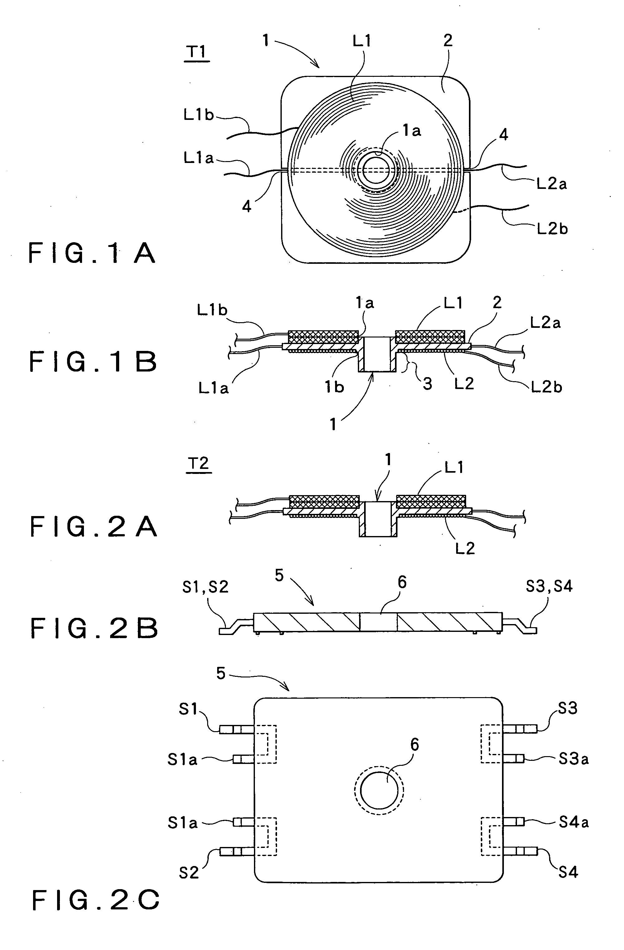
[0035]Referring to FIG. 1 illustrating a representative example of a power transmission transformer for a noncontact power transfer device according to the present invention, the power transmission transformer includes a transmitting coil L1, a drive coil L2, a first bobbin 1, and a collar 2.
[0036]As shown in FIG. 1, the first bobbin 1 is formed of synthetic resin having thermal resistance and insulating properties, and includes: a collar 2 which is approximately quadrangular and includes a cylindrical tubular portion having a predetermined thickness provided thereto; and a winder spindle 1a and a winder spindle 1b on both surfaces of the collar 2 opposed to each other; and further a mating portion 3 for fixing, extending to an end portion of the winder spindle 1b (on the bottom surface side). Then, a plurality of slits 4 made from an edge of the collar 2 to near the winder spindle is provided.
[0037]The second bobbin 5 is formed of flat and approximately quadrangular, synthetic resi...
second embodiment
[0043]As a second embodiment, a power transmission transformer will be described when a mating hole or the like cannot be provided in the surface of the external substrate.
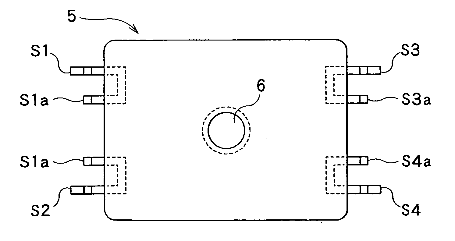
[0044]FIG. 2 shows the assembling of a power transmission transformer T2. In FIG. 2, FIG. 2A is an elevation view of the power transmission transformer T2, and FIG. 2B is an elevation view of a second bobbin, and FIG. 2C is a plan view of the second bobbin.
[0045]As shown in FIG. 2, the power transmission transformer T2 includes a second bobbin 5 having a plurality of external terminals in addition to the power transmission transformer T1 of the first embodiment.
[0046]In the second embodiment, the mating portion 3 provided in the first bobbin of the power transmission transformer T1 in the first embodiment is fitted in the mating hole 6 provided in the second bobbin to be fixed. In addition, when bad fit or the like may be feared at the time of fitting, it may be desirable to fix together with an adhesive agent or ...
third embodiment
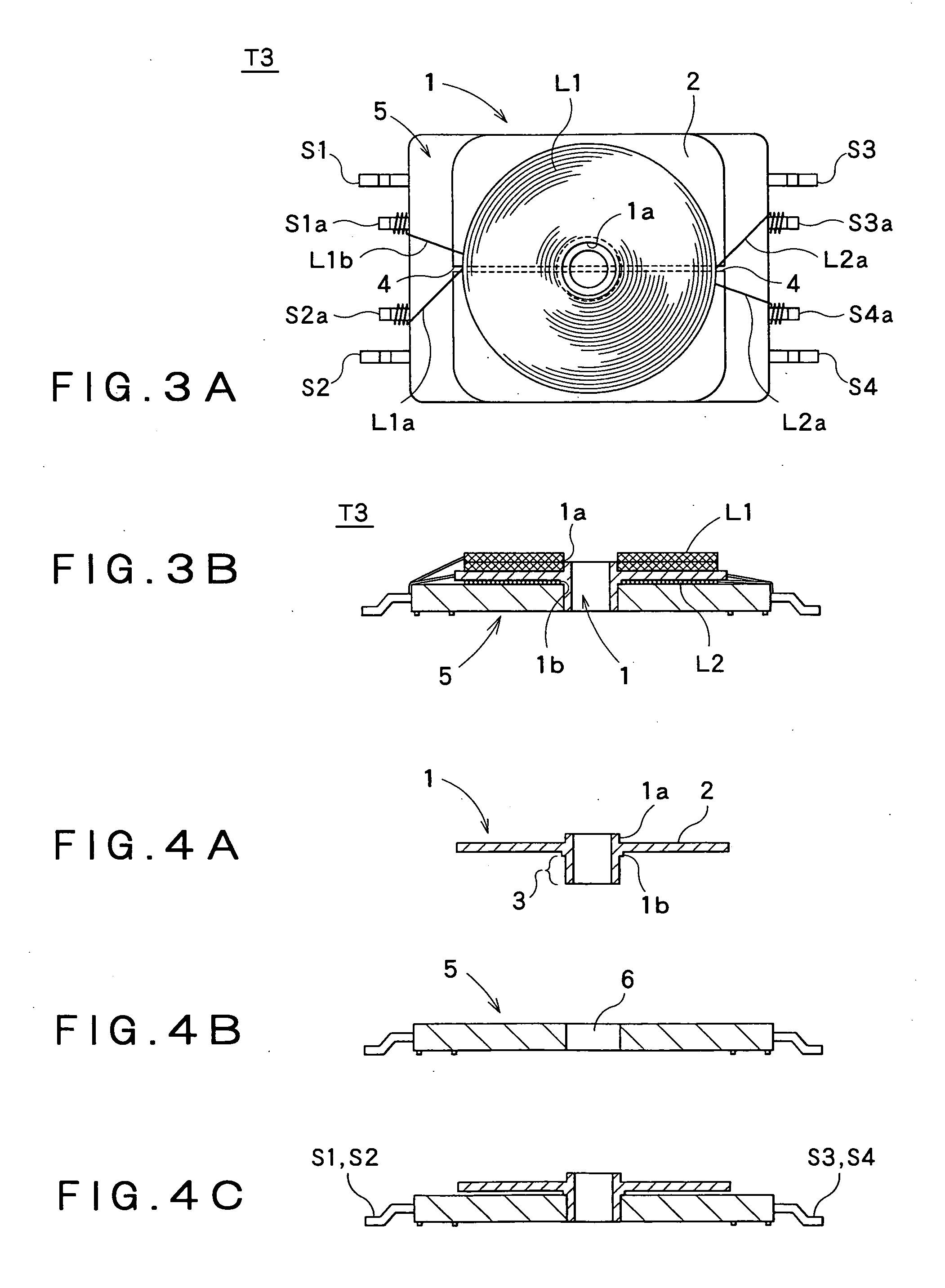
[0050]As a third embodiment, a power transmission transformer T3 will be described that is most suitable when the drive coil L2 has a comparatively large winding number, and the coil has a degree of freedom of winding.
[0051]In FIG. 3, FIG. 3A is a plan view of the power transmission transformer T3 and FIG. 3B is an elevation view thereof.
[0052]FIG. 4 shows the assembling of the first bobbin and the second bobbin. FIG. 4A shows the first bobbin, and FIG. 4B shows the second bobbin, and FIG. 4C shows that the first bobbin and the second bobbin are fitted together.
[0053]As shown in FIG. 4, the power transmission transformer T3 is shown in FIG. 4C illustrating that the mating portions of the first bobbin (FIG. 4A) and the second bobbin (FIG. 4B) described in the first and second embodiments are beforehand fitted together.
[0054]In the power transmission transformer T3, as shown in FIG. 3, first, the drive coil L2 is formed by winding urethane-coated electrical conductor around the winder...
PUM
| Property | Measurement | Unit |
|---|---|---|
| magnetic | aaaaa | aaaaa |
| electric power | aaaaa | aaaaa |
| power consumption | aaaaa | aaaaa |
Abstract
Description
Claims
Application Information
 - R&D
- Intellectual Property
- Life Sciences
- Materials
- Tech Scout
- Unparalleled Data Quality
- Higher Quality Content
- 60% Fewer Hallucinations
Browse by: Latest US Patents, China's latest patents, Technical Efficacy Thesaurus, Application Domain, Technology Topic, Popular Technical Reports.
© 2025 PatSnap. All rights reserved.Legal|Privacy policy|Modern Slavery Act Transparency Statement|Sitemap|About US| Contact US: help@patsnap.com


