Transmitter Device, Bridge Device, and Receiver Device, and Network System Including the Devices

a technology of synchronous systems and receiver devices, applied in data switching networks, synchronisation arrangements, broadcast service distribution, etc., can solve problems such as preventing accurate synchronization of synchronous systems using this route, and not ensuring synchronization

Active Publication Date: 2008-10-16
PANASONIC CORP
View PDF20 Cites 3 Cited by
  • Summary
  • Abstract
  • Description
  • Claims
  • Application Information

AI Technical Summary

Benefits of technology

[0010]This network system allows the receiver device to output visuals and a

Problems solved by technology

However, in a wired network, routing or other processes in the transmission line may cause time-series random time delay variations, hence preventing a synchronous system using this route from having accurate synchronization.
Syste

Method used


Image

  • Transmitter Device, Bridge Device, and Receiver Device, and Network System Including the Devices
  • Transmitter Device, Bridge Device, and Receiver Device, and Network System Including the Devices
  • Transmitter Device, Bridge Device, and Receiver Device, and Network System Including the Devices

Examples


exemplary embodiment 1

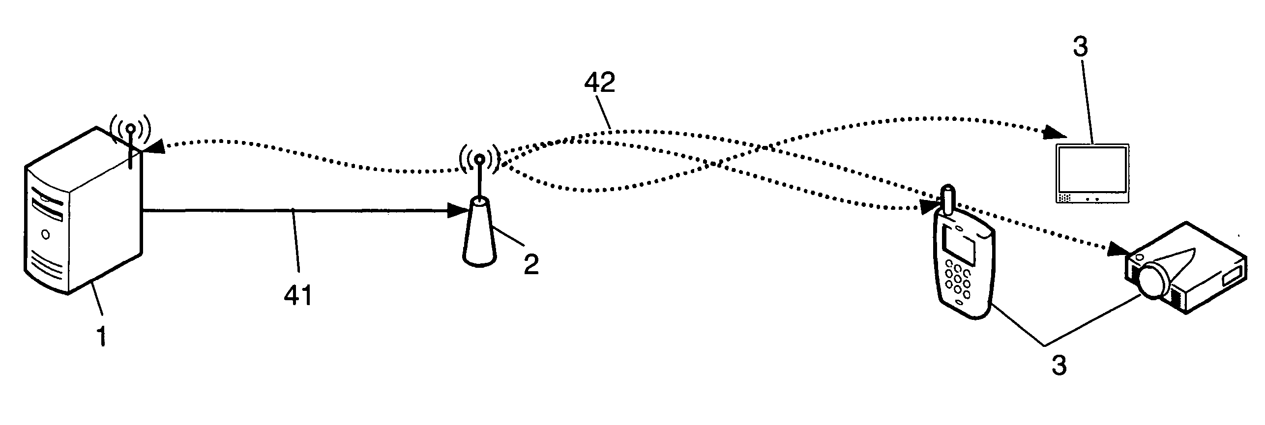
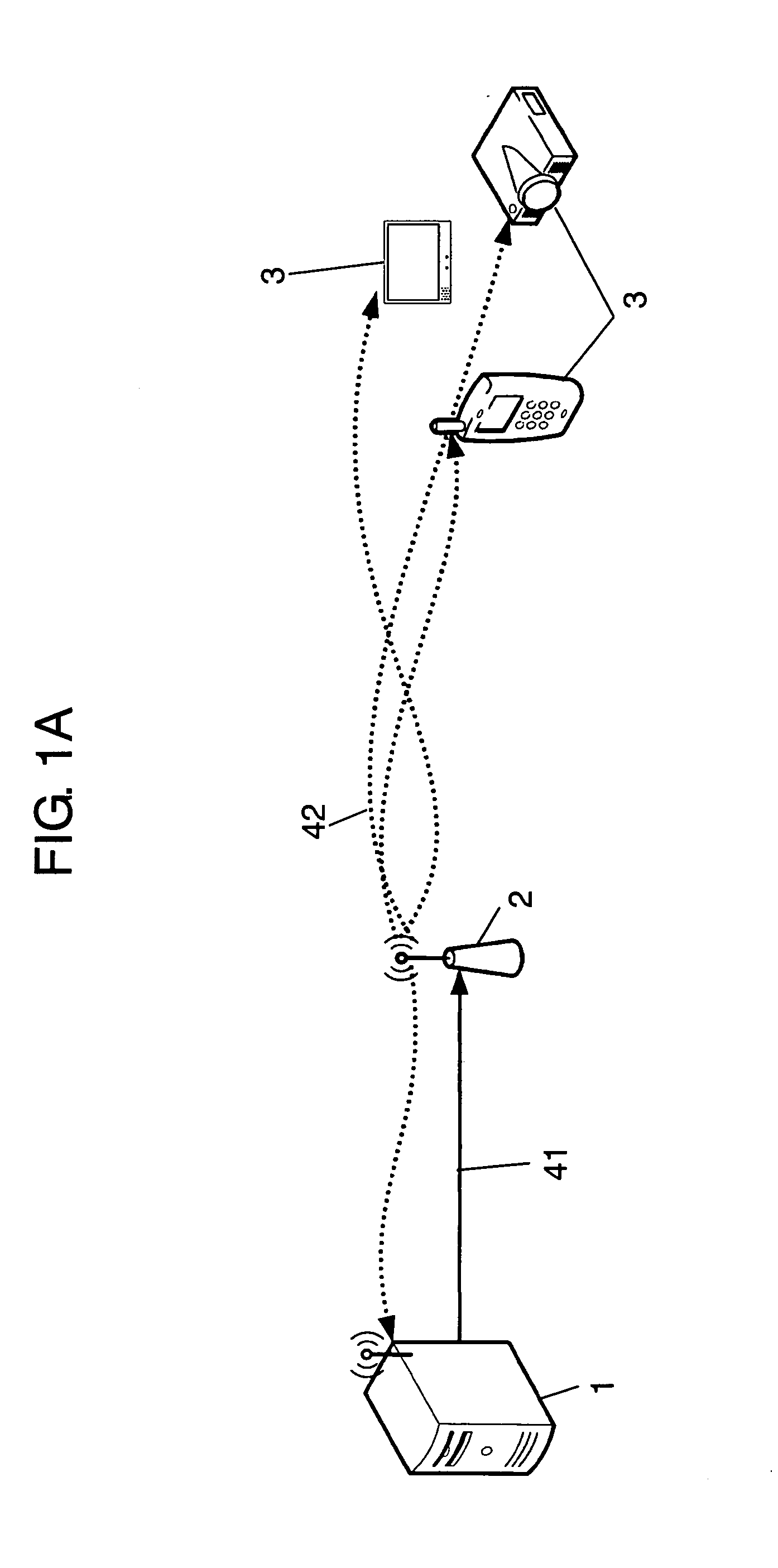
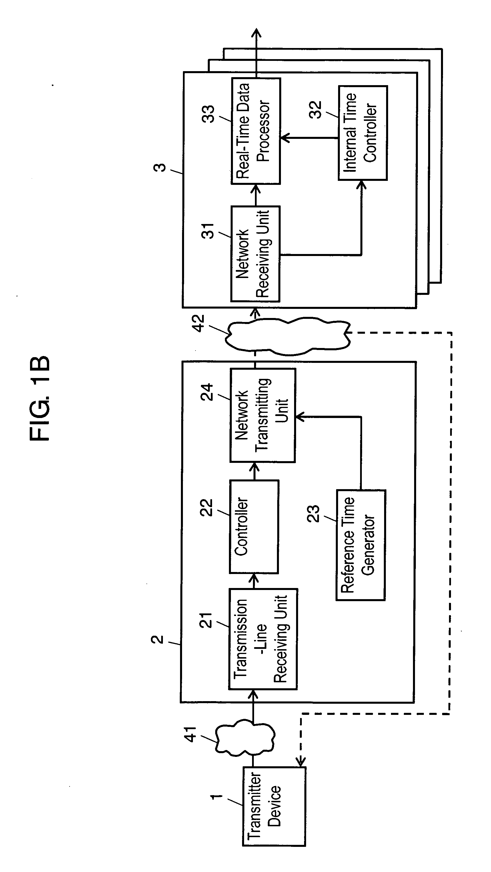
[0046]FIG. 1A is a schematic diagram of a network system in accordance with Exemplary Embodiment 1 of the present invention. In this system, contents data, such as visuals and audios, are transmitted, received, and decoded, so that the visuals and audios are output. In other words, the contents data requires real-time property, and contained in real-time data. This network system includes transmitter device 1 for transmitting the real-time data, bridge device 2 for receiving the real-time data transmitted from transmitter device 1 and transmitting the data, receiver devices 3 for receiving the real-time data transmitted from the bridge device, transmission line 41 for transmitting the real-time data transmitted from transmitter device 1, and wireless network 24 for transmitting the data transmitted from the bridge device. The network system generally includes plural receiver devices 3, but may include single receiver device 3.

[0047]In the network system according to Embodiment 1, th...

exemplary embodiment 2

[0064]FIG. 6 is a block diagram of reference time generator 23A of a bridge device in accordance with Exemplary Embodiment 2 of the present invention. A network system of Embodiment 2 includes reference time generator 23A instead of reference time generator 23 of bridge device 2 in the network system of Embodiment 1 shown in FIGS. 1 to 5. The other elements are the same as those of the network system of Embodiment 1, and their descriptions will be omitted.

[0065]Reference time generator 23A includes internal time generator 234, internal time updater 235, internal time counter 231, and reference time supplier 232.

[0066]Internal time generator 234 modifies a reference time according to a program clock reference (PCR) described in a MPEG TS packet that has been delivered in a RTP packet received via transmission-line receiving unit 21 so as to generates modified reference time. Specifically, the modified reference time is provided by subtracting the average of transmission delay time pr...


PUM


Abstract

A network system includes a transmitting apparatus; a transmission path; a relaying apparatus that receives real time information transmitted through the transmission path; a wireless network; and a receiving apparatus that receives data transmitted through the wireless network. The relaying apparatus has a reference time generating part that generates a reference time independently of the transmitting apparatus; and a network transmitting part that transmits both the real time information received from the transmitting apparatus and the reference time via the wireless network. The receiving apparatus has a network receiving part that receives the real time information and reference time transmitted through the wireless network; an internal time management part that generates an internal time from the reference time received by the wireless network receiving part; and a real time information processing part that decodes the real time information received by the wireless network receiving part to reproduce the content data and that then outputs the content data, based on the internal time generated by the internal time management part. This network system allows the receiving apparatus to synchronize and output video and audio, regardless of singularity or plurality of the receiving apparatus.

Description

TECHNICAL FIELD[0001]The present invention relates to a transmitter device, bridge device, and receiver device for transmitting and receiving data requiring a real-time property, and to a network system including them.BACKGROUND OF THE INVENTION[0002]In transportation facilities for tourists, such as an airplane, a receiver device is provided at each of passenger seats in the facilities for providing various services, such as videos (e.g. movies and satellite broadcasting), audios (e.g. music and news), and interactive contents (e.g. games and shopping). These services are provided by connecting a server storing the videos, audios, and interactive contents to deliver them to each of the passenger seats via a transmission network with communications using various network technologies (e.g. streaming technologies, and file transfer protocols).[0003]A movie service particularly in these services provides the audios supplied from each seat, and the visuals supplied from a large screen o...

Claims


Application Information

Patent Timeline
IPC IPC(8): H04J3/00H04L12/66H04L7/00H04N7/173H04W4/06H04W56/00H04W84/12
CPCH04L29/06027H04N21/2368H04N21/4307H04N21/4341H04N21/43615H04N21/43637H04W4/02H04W56/00H04W84/005H04W88/02H04W88/04H04L65/80H04L67/18H04L69/28H04N21/43078H04L67/52H04L12/66H04L65/1101
Inventor KUSHIKI, YUSUKEHIGASHIDA, MASAAKITANIGUCHI, KENSHI
Owner PANASONIC CORP
Why Eureka
Try Eureka