At-Home Hearing Aid Testing and Clearing System

a technology for hearing aids and clearing systems, applied in hearing aid testing/monitoring, deaf-aid sets, electrical appliances, etc., can solve the problems of inability to improve the consequently ponderous process of patients, inhibit the market penetration of hearing aids, and reduce the diagnostic accuracy of patients. , to achieve the effect of simplifying the diagnostic process

Inactive Publication Date: 2008-10-16
JOHNSON & JOHNSON CONSUMER COPANIES
View PDF99 Cites 39 Cited by
  • Summary
  • Abstract
  • Description
  • Claims
  • Application Information

AI Technical Summary

Benefits of technology

[0015]It is therefore an object of the present invention to simplify the process of diagnostic testing and maintaining hea

Problems solved by technology

Year after year, market penetration has increased little, making it apparent that factors other than user need have inhibited market penetration of hearing aids.
Resources have not gone to improving the consequently ponderous process which patients face in purchasing, using, and maintaining a hearing aid.
When a hearing aid is inserted into the ear canal, it is susceptible to the effects of cerumen accumulation and migration.
Cerumen often mixes with sloughed off skin and dirt, further impairing the performance of the hearing aid.
Acoustic speakers in most modern hearing aids are particularly susceptible to performance problems and damage from cerumen accumulation; initially, cerumen blocks the speaker port, occluding the acoustic path, in turn preventing sound waves from reaching the tympanic membrane.
Eventually, the cerumen can penetrate the receiver housing, damaging the sensitive mechanical and electrical components whose failure necessitates repair or replacement of the hearing aid.
Not only is the cost in time and money significant, but also individuals are uncertain whether their hearing is worsening or the hearing aid is malfunctioning.
The net effect is diminished hearing-aid performance—and thus a diminished quality of life.
While pro

Method used


Image

  • At-Home Hearing Aid Testing and Clearing System
  • At-Home Hearing Aid Testing and Clearing System
  • At-Home Hearing Aid Testing and Clearing System

Examples


Embodiment Construction

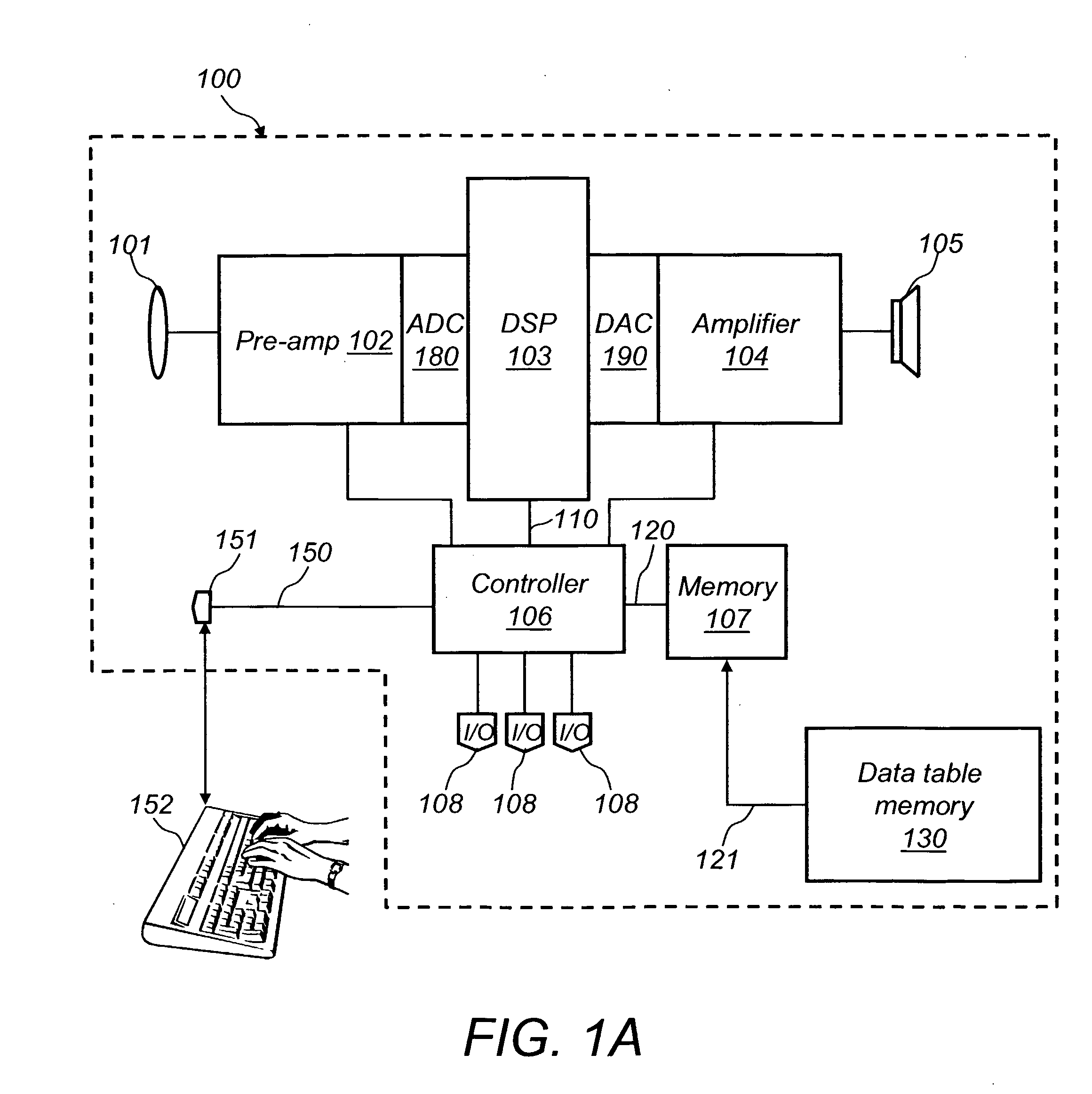
[0047]FIG. 1A is a block diagram illustrating the components of a basic prior art hearing aid 100, and basic operation of a programmable hearing aid, which is programmable by a serial interface in order to be optimized for an individual patient's hearing needs and preferences.

[0048]Hearing aid 100 includes the following conventional components: a microphone 101, a pre-amplifier (pre-amp) 102, an analog-to-digital converter (ADC) 180, a digital signal processor (DSP) 103, a digital-to-analog converter (DAC) 190, an amplifier 104, an output speaker 105, a data table memory 130, an address and data bus 121, a memory 107, a controller 106, an address and data bus 120, an address and data bus 110, a plurality of input / output devices (I / O) 108, a programming connection 150, and a socket connector 151.

[0049]With hearing aid 100 in a user's ear, sound is collected as an analog signal in microphone 101. This signal is amplified using pre-amp 102, is converted from analog to digital in ADC 18...


PUM


Abstract

The present invention is an apparatus for and method of remotely, automatically, and routinely conducting diagnostic testing on a programmable hearing aid to ensure that it is functioning as intended when optimized for an individual's needs and preferences. Because hearing aids deteriorate with time and buildup of earwax, individuals can be uncertain whether their hearing is worsening or the hearing aid is malfunctioning. The net effect is diminished hearing aid performance and thus diminished quality of life. The present invention tests the hearing aid for proper function as frequently as daily. Additionally, the present invention includes elements (201, 202) that enable the apparatus to perform a cleaning process to effectively remove earwax and other undesirable debris from the hearing aid. The cleaning process can occur prior to the diagnostic testing or as a result of the diagnostic testing.

Description

CROSS REFERENCE TO RELATED APPLICATION[0001]This application claims the benefit of U.S. Provisional Application Nos. 60 / 579,479 filed Jun. 14, 2004 and 60 / 579,220 filed Jun. 14, 2004, assigned to the assignee of this application and incorporated by reference herein.FIELD OF THE INVENTION[0002]The present invention relates to hearing aids, specifically to a method of and apparatus for automatically testing an individual's hearing aid in the individual's home as frequently as daily in order to determine whether the hearing aid needs to be cleaned or serviced and performing the cleaning process if deemed necessary.BACKGROUND OF THE INVENTION[0003]About two million hearing aids are sold annually in the U.S., generating $2.6 billion in revenue. Although 28 million Americans are hearing impaired, only six million use hearing aids. Year after year, market penetration has increased little, making it apparent that factors other than user need have inhibited market penetration of hearing aids...

Claims


Application Information

Patent Timeline
IPC IPC(8): H04R29/00H04R25/00
CPCH04R25/30H04R25/505H04R25/654H04R2460/17
Inventor CRONIN, JOHNNARSANA, TUSHARBURROWS, MARK
Owner JOHNSON & JOHNSON CONSUMER COPANIES
Why Eureka
Try Eureka