Tension Wheel Hub in a Rotor System for Wind and Water Turbines

a technology of rotor system and fluid flow turbine, which is applied in the direction of rotors, machines/engines, renewable energy generation, etc., can solve the problems of not harnessing wind energy at the cost, and achieve the effects of reducing the length of the blade, sound structural, and increasing the swept area of the rotor

Inactive Publication Date: 2008-10-16
UNITED TECH CORP
View PDF8 Cites 24 Cited by
  • Summary
  • Abstract
  • Description
  • Claims
  • Application Information

AI Technical Summary

Benefits of technology

[0012]The invention has the advantage of limiting blade length to materials and designs which provide sound structural margins but increase the rotor swept area (rotor diameter) by replacing a conventional hub design with a tension wheel hub arrangement with blades attached to the rim of the tension wheel.

Problems solved by technology

While the increase in swept area is accomplished with blades of a length, which meets suitable structural requirements, it does so at the cost of not harnessing the wind energy in the area of the rotor circumscribed by the tension wheel hub.

Method used


Image

  • Tension Wheel Hub in a Rotor System for Wind and Water Turbines
  • Tension Wheel Hub in a Rotor System for Wind and Water Turbines
  • Tension Wheel Hub in a Rotor System for Wind and Water Turbines

Examples


Embodiment Construction

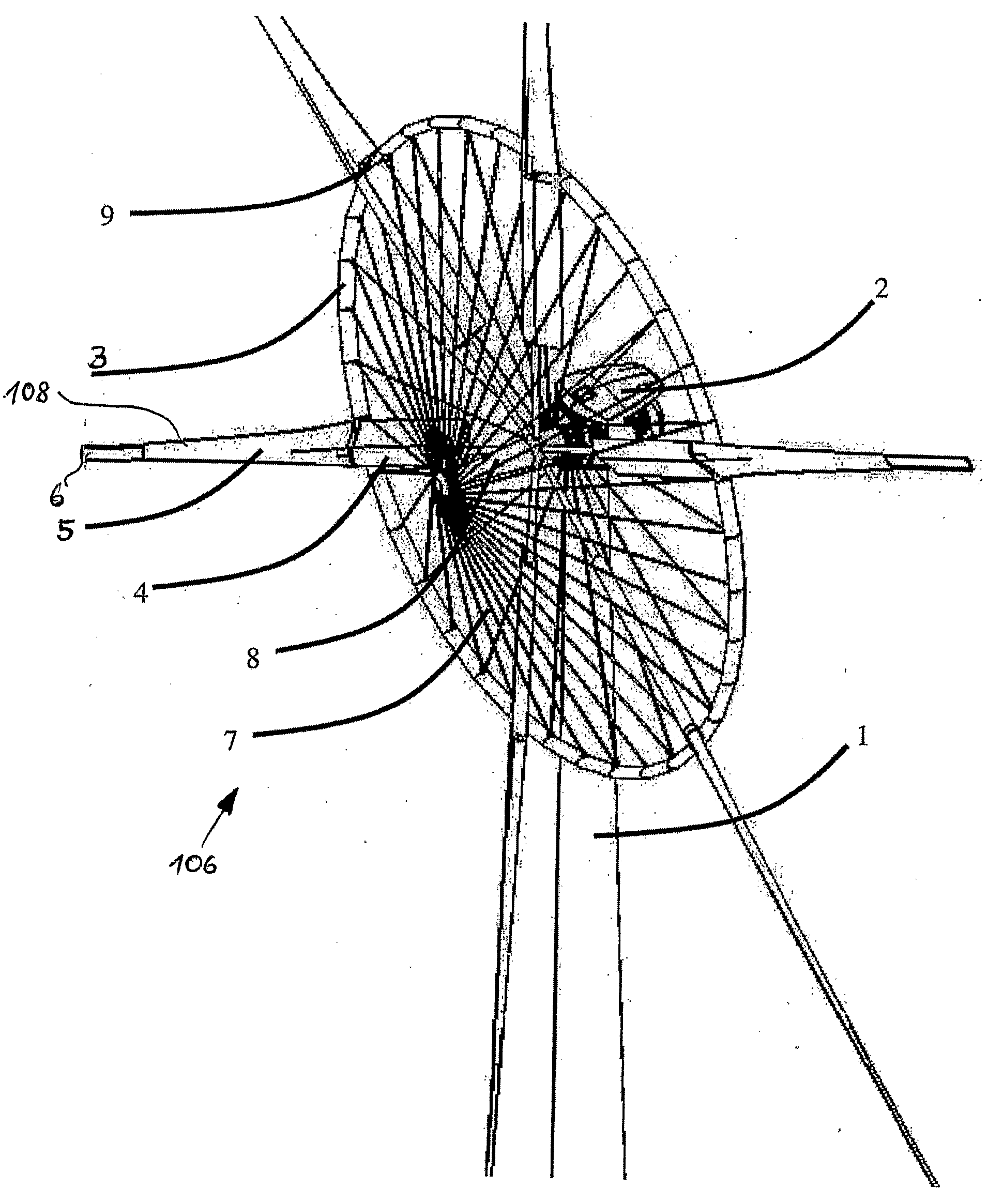
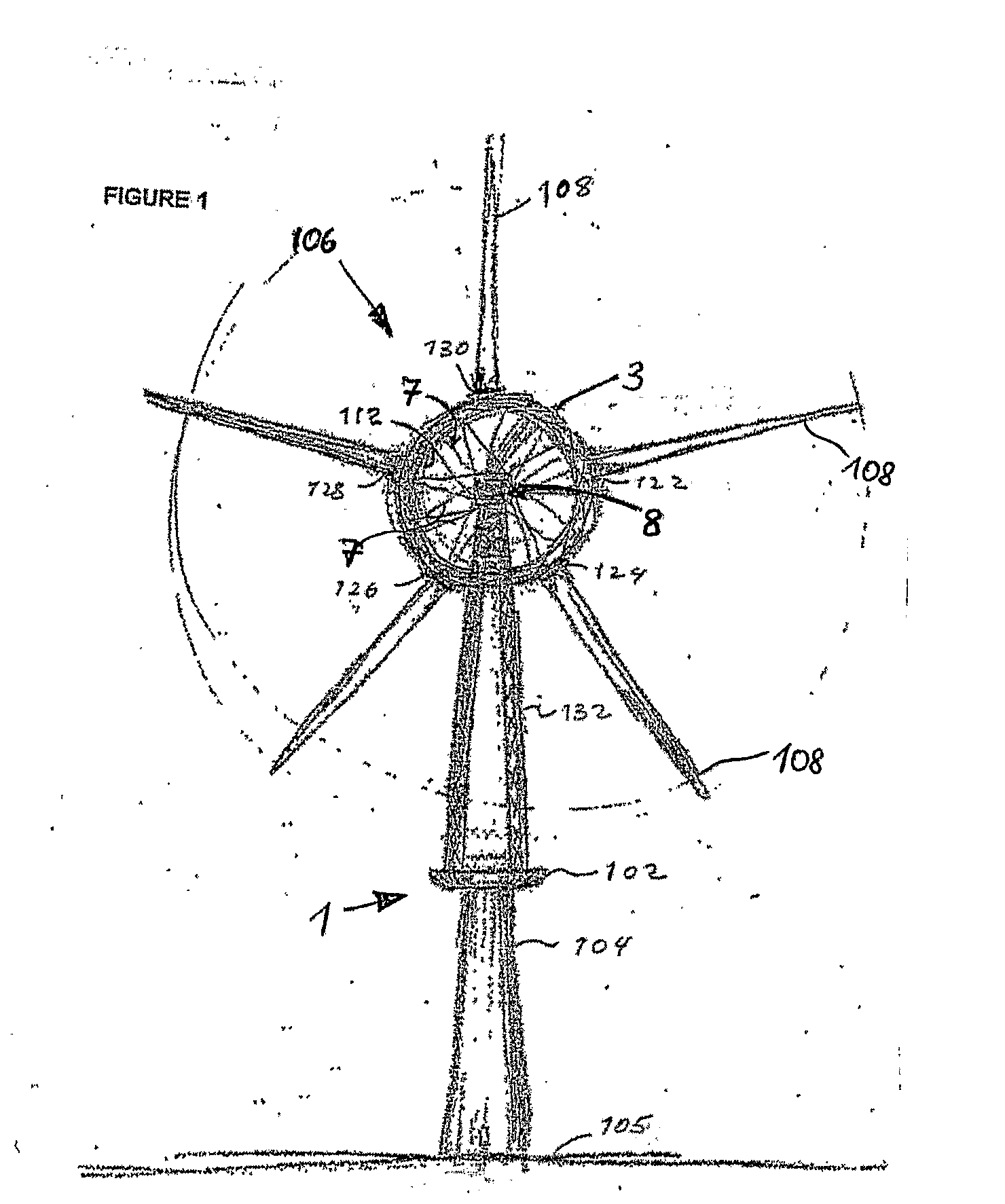
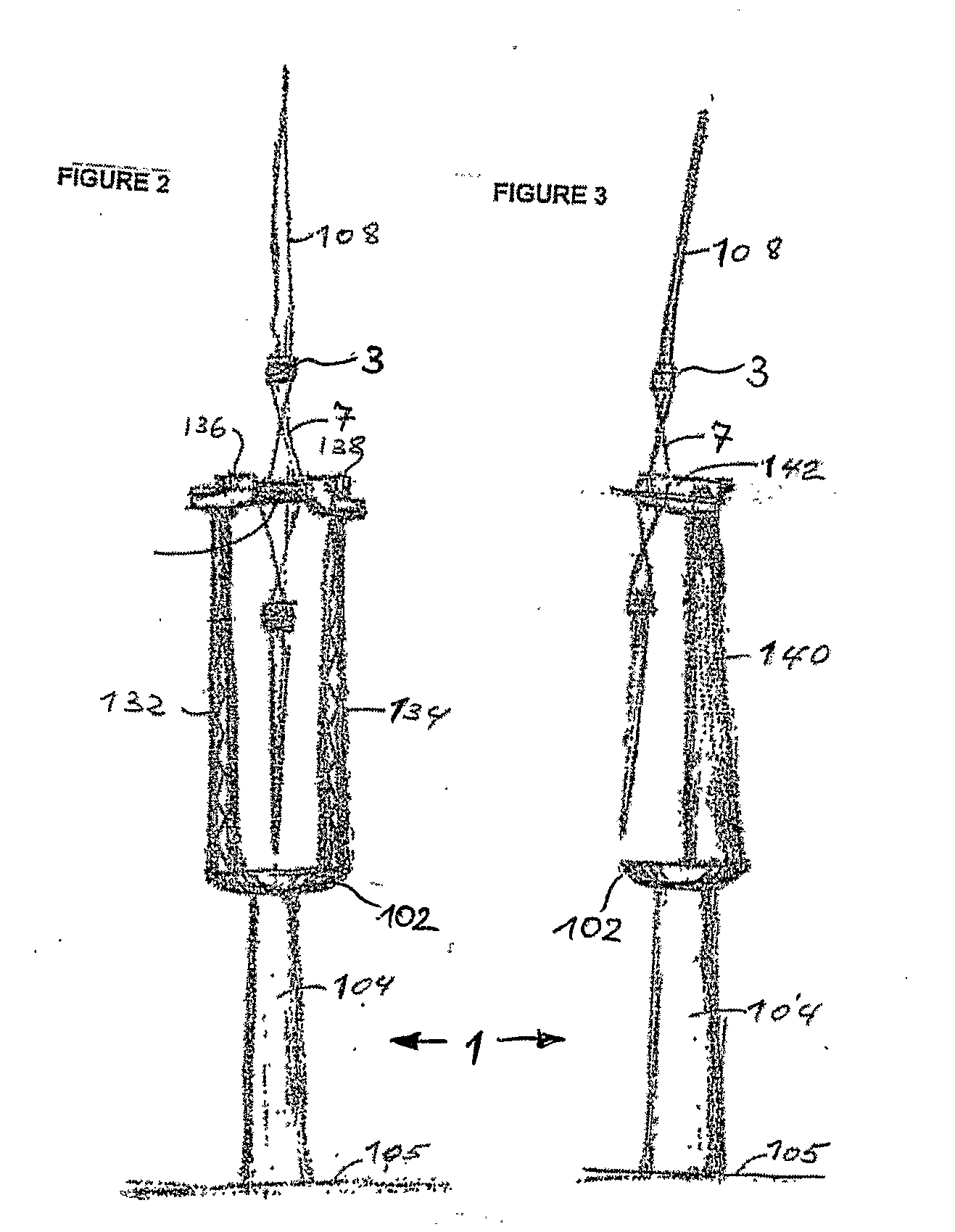
[0025]Refer to FIG. 1, which is a front view of a rotor system and fork-top tower 1 in which applicant's invention is embodied. The wind power-generating device includes an electric generator housed in a turbine nacelle 2, which is mounted by a fork-top section, 132, to a yaw base 102 atop a tall tower structure 104 anchored to the ground 105. The turbine yaw base 102 is free to rotate in the horizontal plane such that it tends to remain in the path of prevailing wind current. The turbine has a tension wheel hub assembly 106 comprising a tension wheel mounted on a hub 8. The tension wheel consist of a rim structure 3 supported by spokes 7 attached to the hub 8. The rim structure 3 (shown in more detail in FIGS. 4 and 5) comprises an inner rim 112 (to which the spokes 7 are attached) and an outer rim 107. The main blades 108 are attached to the outer rim 107. The blades 108 rotate in response to wind current. Each blade root 122, 124, 126, 128, 130 is mounted to the tension wheel out...


PUM


Abstract

A rotor system for a fluid-flow turbine comprising a hub mounted on a shaft, a plurality of rotor blades, and a tension wheel, the tension wheel comprising a rim structure mounted to the hub by a plurality of spokes. Each rotor blade is attached to the rim structure of the tension wheel. The lost energy in the area of the rotor circumscribed by the tension wheel rim structure is captured by applying airfoils, such as blades or sails, to the spokes of the tension wheel and/or an inner section of the rotor blades.

Description

BACKGROUND OF THE INVENTION[0001]1. Field of the Invention[0002]The invention relates to a rotor system for a fluid-flow turbine comprising a hub mounted on a shaft, and a plurality of rotor blades.[0003]2. Prior Art[0004]In a typical horizontal-axis wind turbine, a nacelle is mounted on a tall vertical tower. The nacelle houses power-transmitting mechanisms, electrical equipment and supports a rotor system at one end. Rotor systems for horizontal-axis wind turbines ordinarily include one or more blades attached to a rotor hub on a shaft. Wind flow turns the rotor, which turns the shaft in the nacelle. The shaft turns gears that transmit torque to electric generators. The nacelle typically pivots about the vertical tower to take advantage of wind flowing from any direction. The pivoting about this vertical-axis in response to changes in wind direction is known as yaw or yaw response and the vertical-axis is referred to as the yaw-axis. As wind moves past the blades with enough speed...

Claims


Application Information

Patent Timeline
Patent Type & Authority Applications(United States)
IPC IPC(8): F03D1/06F03B3/14
CPCF03B3/14F03B17/061F03D1/0608F03D1/0658F05B2240/2211F05B2250/36Y02E10/223Y02E10/28Y02E10/721Y02E10/20Y02E10/72F03D1/06
Inventor DEHLSEN, JAMES G. P.
Owner UNITED TECH CORP
Why Eureka
Try Eureka