Knee-Ankle-Foot Orthosis with Load Brake

a technology of load brake and knee, applied in the field of knee-ankle-foot orthosis, can solve the problems of inability to ascend stairs, excessive diameter of brake discs, and inability to move in the direction of medical science, etc., and achieve the effect of sufficient braking for

Inactive Publication Date: 2008-10-16
IMASEN ENG CORP +1
View PDF3 Cites 21 Cited by
  • Summary
  • Abstract
  • Description
  • Claims
  • Application Information

AI Technical Summary

Benefits of technology

[0007]As described above, the locking method with claw has the advantage that a knee axis can be securely locked, but has the problem that an extra motion is needed to shift it to the unlocked state because of the biting phenomenon of the claw. In addition, in the case of locking with a claw, the locking position is always limited to a constant knee position, normally its extended position. When the patient ascends stairs and slopes, his knee is needed to be locked in its sligh

Problems solved by technology

As described above, the locking method with claw has the advantage that a knee axis can be securely locked, but has the problem that an extra motion is needed to shift it to the unlocked state because of the biting phenomenon of the claw.
In addition, in the case of locking with a claw, the locking position is always limited to a constant knee position, normally its extended position.
When the patient ascends stairs and slopes, his knee is needed to be locked in its slightly

Method used


Image

  • Knee-Ankle-Foot Orthosis with Load Brake
  • Knee-Ankle-Foot Orthosis with Load Brake
  • Knee-Ankle-Foot Orthosis with Load Brake

Examples


first embodiment

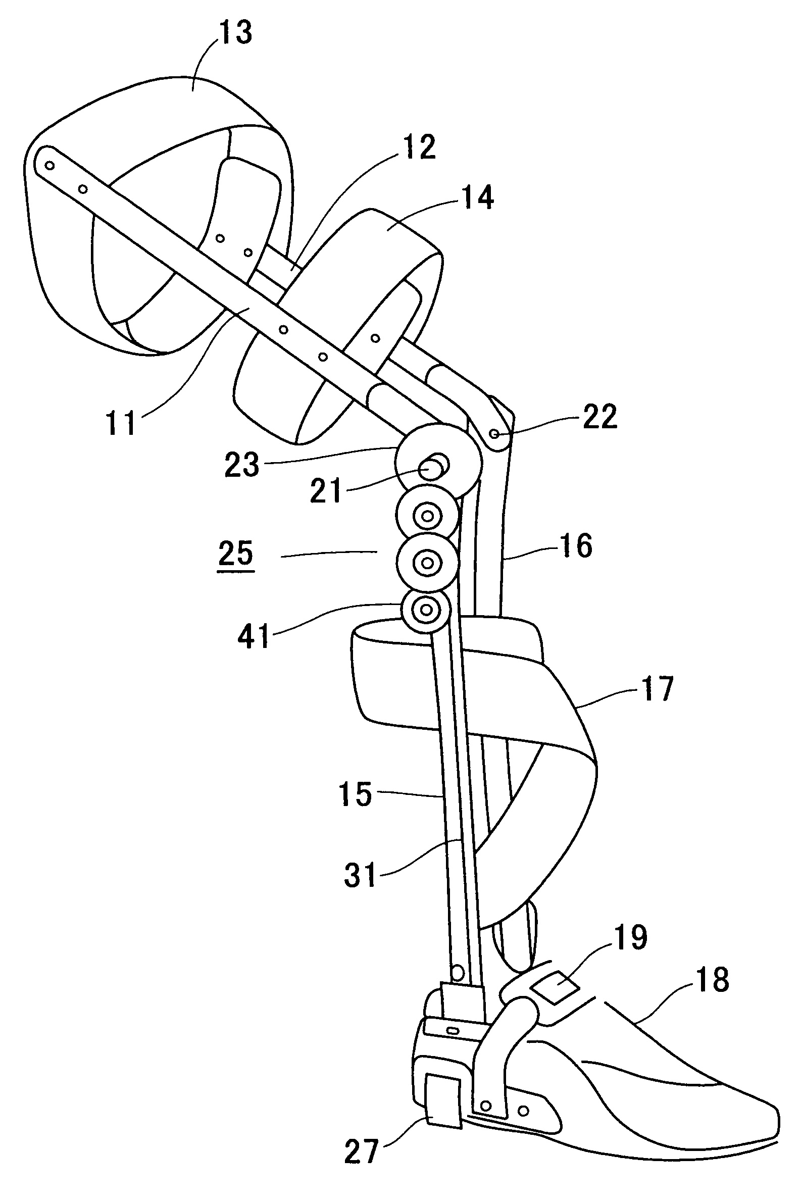
[0042]FIG. 1 is a perspective view showing a knee-ankle-foot orthosis with load brake in accordance with the present invention. Thigh bands 13 and 14 are attached to two left and right thigh frames 11 and 12. Knee axes 21 and 22 are secured to lower ends of the thigh frames 11 and 12, and leg frames 15 and 16 are pivotally attached to the knee axes 21 and 22. A leg band 17 is attached to the leg frames 15 and 16. Afoot holding portion 18 is secured to lower ends of the leg frames 15 and 16, and a foot band 19 is attached to the foot holding portion 18. A knee axis gear 23 is secured to the knee axis 21 located on the inner side of the orthosis, and the knee axis gear 23 engages with a three-stage speed increasing gear train 25 which is rotatably supported on the leg frame 15.

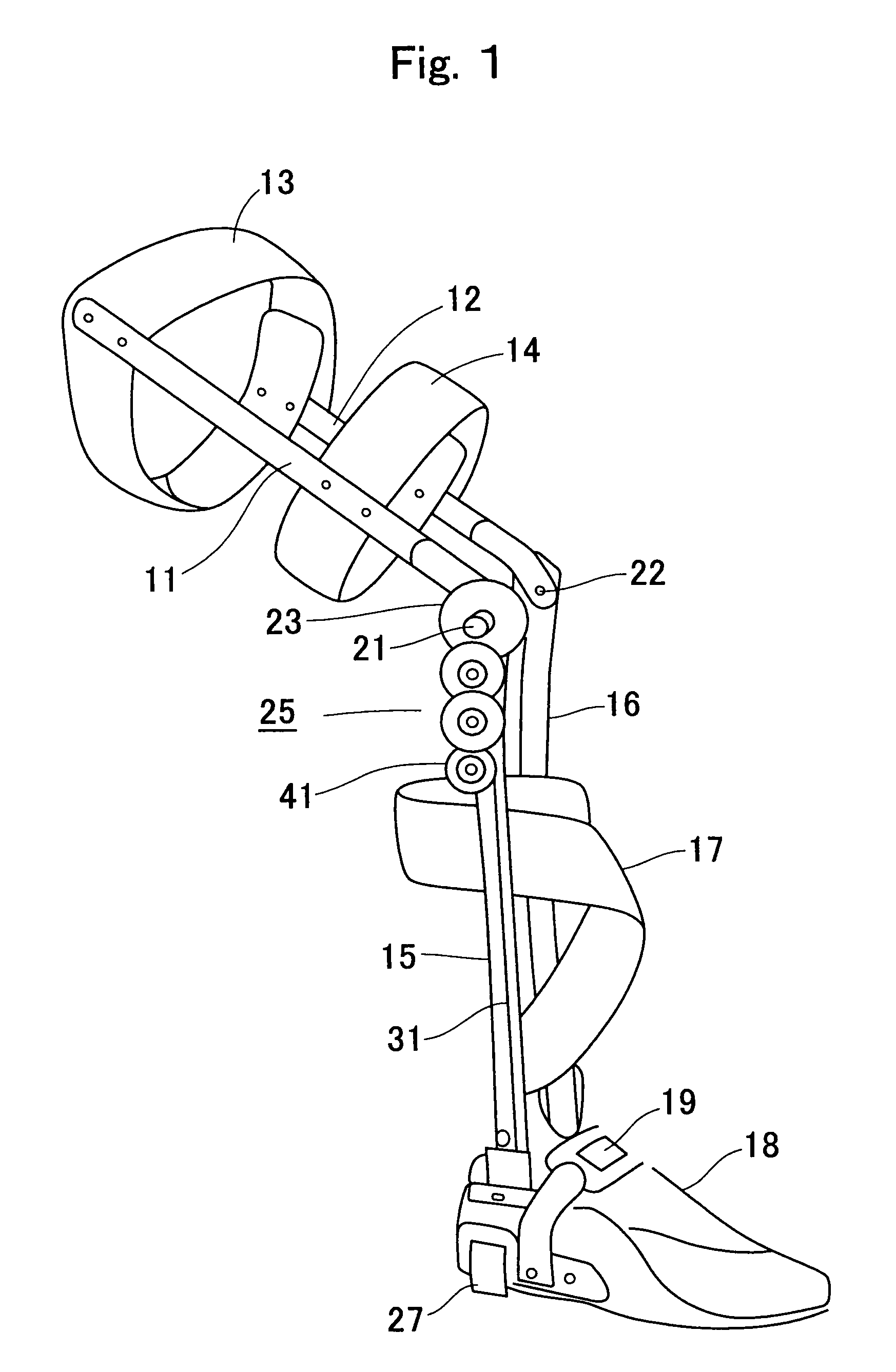
[0043]FIG. 2 is a side view showing the foot holding portion 18. A side plate 26 is secured to a side part of the foot holding portion 18 to support the leg frame 15. A first lever 27 is held on a rear side of t...

second embodiment

[0049]FIG. 4 is a perspective view showing a knee axis control unit of the knee-ankle-foot orthosis in a second embodiment, in which mechanisms such as the brake drum 41, the speed increasing gear train 25, etc. are formed into a unit. FIG. 5 is a rear view of the knee axis control unit. A unit housing 70 is secured to the leg frame 15, and is formed integrally with a leg arm 71. Two screw holes 71A and 71A are provided in the leg arm 71 for securing the unit housing 70 to the leg frame 15. On the opposite side of the unit housing 70, a thigh arm 72 is pivotally supported with the unit housing 70 via a knee axis 73. Two screw holes 72A and 72A are provided in the thigh arm 72 for securing the thigh arm 72 to the thigh frame 11. In addition to the knee axis 73, a first-stage axis 74, a second-stage axis 75 and a third-stage axis 76 are provided in the unit housing 70. Two wire holes 77 and 77 are provided in a side surface of the unit housing 70 on the side of the leg arm 71, and the...

third embodiment

[0053]FIG. 7 is a perspective view showing a knee axis control unit of the knee-ankle-foot orthosis in a third embodiment, in which mechanisms including a one-way clutch are formed into a unit. A rear view is identical to FIG. 5 so as not to be specifically shown. Like reference characters will be used to designate members common to those shown in FIG. 4, and descriptions thereof will be omitted. In the present embodiment, the axial length of a final third-stage axis 91 is made slightly longer than those of the other axes 73, 74 and 75, and accordingly, a unit housing 90 is configured to have an increased wall thickness around the third-stage axis 91 for accommodating the one-way clutch.

[0054]FIG. 8 is a longitudinal sectional view of a knee axis control unit, to which the one-way clutch is added. Like reference characters will be used to designate members common to those shown in FIG. 6, and descriptions thereof will be omitted. The final third-stage axis 91 is rotatably supported ...


PUM


Abstract

A knee-ankle-foot orthosis in accordance with the present invention can smoothly shift from the stance phase to the swing phase thereof. Namely, the knee-ankle-foot orthosis capable of securely locking a patient's knee in a desired angular position thereof with a load of his body weight, and immediately shifting his knee to the unlocked state without requiring any extra motion when the load disappears is provided.
As shown in FIG. 1, the speed of the rotation of a knee axis gear 23 adapted to transmit the rotation of a knee axis 21 is increased by eight times with a speed increasing gear train 25, and is transmitted to a brake drum 41. A wire 31 wound around the brake drum 41 is connected to first and second levers 27 and 28 as load detecting members. When a foot holding portion 18 contacts the ground and the first lever 27 is stepped down, the wire 31 is pulled downwardly with a load of his body weight, whereby brakes are applied. The brake torque is increased by eight times, and is transmitted to the knee axis 21. Consequently, even with a small force due to the load of his body weight, the knee-ankle-foot orthosis can be securely locked with a braking method to prevent giving way thereof. In addition, since the braking method is used, shifting to the unlocked state can be smoothly achieved.

Description

TECHNICAL FIELD[0001]The present invention relates to a knee-ankle-foot orthosis adapted to provide independent walking means for a walking impaired person whose lower limb is paralyzed or whose muscle function is lost due to his spinal cord injury, cerebrovascular disorder, external wound etc.BACKGROUND ART[0002]The knee-ankle-foot orthosis exhibits problems in locking and unlocking of a knee axis thereof. The most elementary knee-ankle-foot orthosis is provided with a device of locking and unlocking a thigh frame and a leg frame by hand, and upon walking, a patient locks the thigh frame and the leg frame, whereas, upon sitting, etc., he unlocks them to flex his knee. With the knee-ankle-foot orthosis thus arranged, however, a knee axis thereof is fixed upon walking so as to force him to walk with a locked knee. Consequently, his gait becomes unnatural, and he is forced to bear an increased burden. It is ideal for the knee-ankle-foot orthosis to be locked in the stance phase for su...

Claims


Application Information

Patent Timeline
IPC IPC(8): A61F5/00
CPCA61F5/0102A61F2005/0162
Inventor GENDA, EIICHIOHTA, KAZUSHIGESUZUKI, MITSUHISAOTSUKA, SHIGERUYAMAMOTO, KOUJI
Owner IMASEN ENG CORP
Why Eureka
Try Eureka