Fault location estimation system, fault location estimation method, and fault location estimation program for multiple faults in logic circuit

Active Publication Date: 2008-10-16
RENESAS ELECTRONICS CORP
View PDF5 Cites 31 Cited by
  • Summary
  • Abstract
  • Description
  • Claims
  • Application Information

AI Technical Summary

Benefits of technology

[0061]In view of the foregoing, it is an object of the present invention to provide a fault location estimation system

Problems solved by technology

However, the fan-in trace of a recent LSI circuit with millions of gates results in a huge number of combinations, for example, ten thousand nodes, even if the number of combinations is narrowed to one hundredth.
So, the conventional system, if applied to a large-scale circuit, requires a huge amount of calculation and an impractical diagnostic time.
However, when multiple faults occur at the same time, the propagation path may differ from that of a single fault because the error propagating paths affect each other.
In this case, because the multiple-fault combination that accounts for all error outputs cannot be found, the diagnostic accuracy may be reduced.
In addition, the checking of fault simulat

Method used


Image

  • Fault location estimation system, fault location estimation method, and fault location estimation program for multiple faults in logic circuit
  • Fault location estimation system, fault location estimation method, and fault location estimation program for multiple faults in logic circuit
  • Fault location estimation system, fault location estimation method, and fault location estimation program for multiple faults in logic circuit

Examples


Embodiment Construction

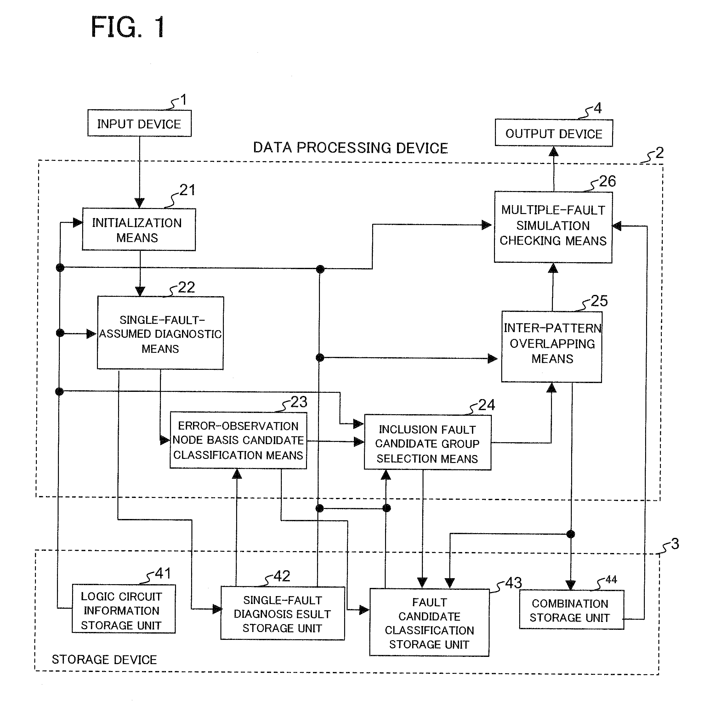
[0134]Next, preferred modes of the present invention will be described in detail with reference to the drawings. FIG. 1 is a diagram showing the configuration of a first example of the present invention. Referring to FIG. 1, the first example of the present invention comprises an input device 1 that has a keyboard or an external interface unit, a data processing device 2 that operates under program control, a storage device 3 such as a hard disk or a memory where information is stored, and an output device 4 such as a display or a printer that is an external interface unit.

[0135]The storage device 3 comprises a logic circuit information storage unit 41, a single-fault diagnosis result storage unit 42, a fault candidate classification storage unit 43, and a combination storage unit 44.

[0136]The logic circuit information storage unit 41 stores the following information:

[0137]logic states of signal lines being processed;

[0138]logic states (expected values) of signal lines when the circ...


PUM


Abstract

A fault location estimation system comprises single-fault-assumed diagnostic means that assumes a single fault and stores fault candidates, fault types, and detected error-observation nodes at which an error arrives from the fault candidates; error-observation node basis candidate classification means that classifies error propagating fault candidates into groups according to error-observation nodes using the fault candidates and the error-observation nodes and stores the groups as fault candidate groups; inclusion fault candidate group selection means that acquires a relation between each fault candidate group and a fault output, calculates an inclusion relation among the fault candidate groups, and, if path information on one fault candidate group includes path information on another fault candidate group, deletes the inclusion fault candidate group; inter-pattern overlapping means that calculates combinations of fault candidate groups that can reproduce a test result in all test patterns by referencing the fault candidates and the fault candidate classification result and extracts fault candidates that are common to fault candidate groups, calculated in multiple patterns, to create a new fault candidate group; and multiple-fault simulation checking means that selects fault candidates from the combinations of fault candidate groups, one from each fault candidate group, performs multiple-fault simulation, compares the simulation result with the test result, and outputs a combination of fault candidate groups which matches relatively well with the test result and has a relatively high fault possibility.

Description

REFERENCE TO RELATED APPLICATION[0001]The present application is claiming the priority of the earlier Japanese patent application No. 2006-274031 filed on Oct. 5, 2006, the entire disclosure thereof being incorporated herein by reference thereto.FIELD OF THE INVENTION[0002]The present invention relates to a multiple-fault location estimation system for estimating multiple fault locations speedily and accurately in a logic circuit.BACKGROUND OF THE INVENTION[0003]As one of conventional fault location estimation systems for multiple faults, reference is made to the fault location estimation system disclosed in Patent Document 1. This fault location estimation system estimates multiple fault locations in a logic circuit by grouping the related internal nodes for each error-observation node where a fault is detected during the test of the logic circuit, performing a single-fault-assumed fault simulation for each internal node, and finding a combination that accounts for entire error out...

Claims


Application Information

Patent Timeline
IPC IPC(8): G01R31/3177G06F9/455G06F11/25
CPCG01R31/318342G06F11/261
Inventor FUNATSU, YUKIHISA
Owner RENESAS ELECTRONICS CORP
Why Eureka
Try Eureka