Gasification reactor

a gasification reactor and gas technology, applied in the direction of gasifier mechanical details, combustible gas purification/modification, combustible gas production, etc., can solve the problems of affecting the operation of the process, affecting the opening of the burner, etc., and achieve the effect of less damag

Inactive Publication Date: 2008-10-23
SHELL OIL CO
View PDF9 Cites 20 Cited by
  • Summary
  • Abstract
  • Description
  • Claims
  • Application Information

AI Technical Summary

Benefits of technology

[0009]Applicants have found that by having a slag deflector above the openings in the membrane wall less or even no slag ingress occurs resulting in less damage.

Problems solved by technology

However when processing feedstocks having a substantial high ash content, more in particular when processing such a feedstock at higher pressures, it is found that the operation of the process becomes more difficult due to ingress of slag into the openings in the membrane wall.
Slag ingress may cause that the area forming the opening for the burner is damaged.

Method used


Image

  • Gasification reactor
  • Gasification reactor
  • Gasification reactor

Examples


Embodiment Construction

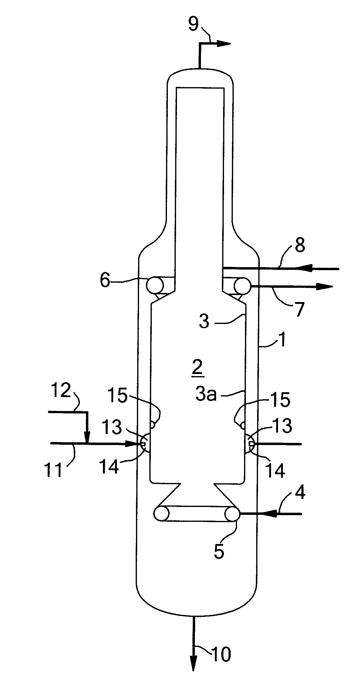
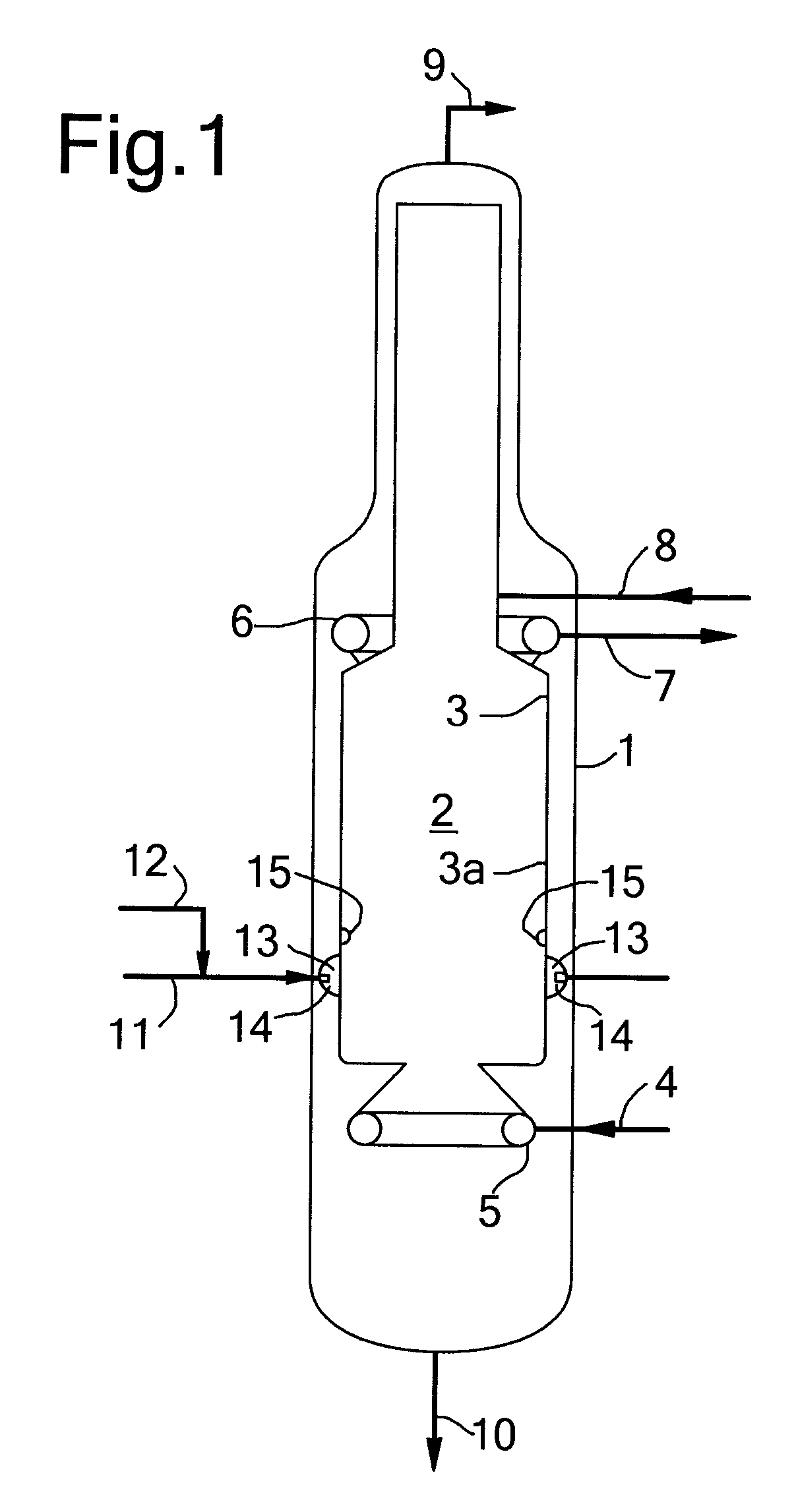
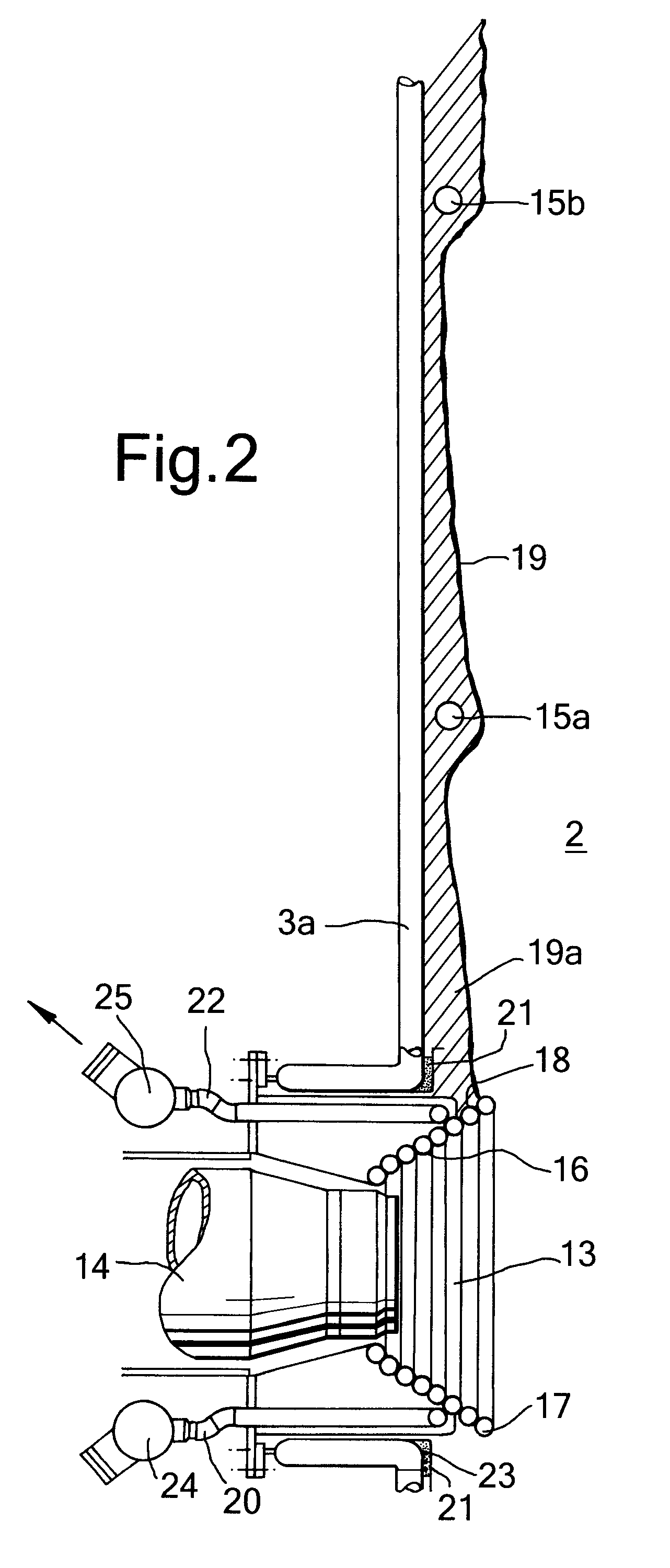
[0016]In a preferred embodiment, the present invention provides a slag deflector above one or more openings in a tubular membrane wall of a gasification reactor. The upper end of the slag deflector may be positioned between 0.1 and 3 times the width of the opening above the upper end of said opening. The slag deflector may be a rim attached to the membrane wall. The rim may be provided with a refractory coating. The deflector may be a conduit attached to the membrane wall provided with an inlet end for a cooling medium and an outlet end for used cooling medium. Said conduit may have a part located at a higher elevation above the opening and lower parts of the conduit extending side ways, such that in use at least part of the downwardly flowing slag is deflected away from the opening. The conduit may be provided with a refractory coating.

[0017]The slag deflector may be made from a low alloy steel with a Cr content up to 5 wt % or a high alloy steel with Cr content above 15 wt %.

[0018...


PUM

PropertyMeasurementUnit
angleaaaaaaaaaa
angleaaaaaaaaaa
pressureaaaaaaaaaa

Abstract

The invention is directed to a gasification reactor comprising a pressure shell, a reaction zone partly bounded by a vertically oriented tubular membrane wall, said wall being provided with one or more openings and wherein attached to the wall and above the opening a slag deflector is present. The invention is also directed to a process to prepare a mixture of hydrogen and carbon monoxide by gasification of a solid or liquid feedstock comprising between 15 and 50 wt % ash in a gasification reactor, wherein the feedstock and an oxygen containing gas and an optional moderator gas are provided to a burner as provided in an opening of the reactor and wherein the gasification in the reaction zone is carried out at a temperature in the range from 1200 to 1800° C. and at a pressure in the range from between 30 and 100 bar.

Description

[0001]This application claims the benefit of European Application No. 07105317.7 filed Mar. 30, 2007 and U.S. Provisional Application No. 60 / 910,095 filed Apr. 4, 2007.FIELD OF THE INVENTION[0002]The invention is directed to a gasification reactor comprising a pressure shell and a reaction zone partly bounded by a vertically oriented tubular membrane wall. The membrane wall is provided with one or more openings.BACKGROUND OF THE INVENTION[0003]Such a gasification reactor is described in U.S. Pat. No. 4,202,672. This publication describes a coal gasification reactor provided with a pressure shell, a reaction zone and a membrane wall, which partly defines the reaction zone. The tubular shaped membrane wall comprises interconnected conduits in which evaporating cooling water is present.[0004]In U.S. Pat. No. 4,959,080 a coal gasification process is described which may be performed in a gasification reactor as above. This publication described that a layer of slag will form on the membr...

Claims


Application Information

Patent Timeline
Patent Type & Authority Applications(United States)
IPC IPC(8): C10K3/06
CPCC10J3/485C10J3/526C10J3/76C10J3/845C10J2200/09C10J2200/152C10J2300/093C10J2300/0959C10J2300/1223C10J2300/1634C10J2300/1846C10K1/101
Inventor VON KOSSAK-GLOWCZEWSKI, THOMAS PAUL
Owner SHELL OIL CO
Why Eureka
Try Eureka