Fossil-Fuel Heated Continuous Steam Generator

a technology of oil-fuel heated steam and continuous steam, which is applied in the direction of steam generation plants, machines/engines, lighting and heating apparatus, etc., can solve the problem of local maximum temperatures in the tube walls being limited

Inactive Publication Date: 2008-10-23
SIEMENS AG
View PDF14 Cites 16 Cited by
  • Summary
  • Abstract
  • Description
  • Claims
  • Application Information

AI Technical Summary

Benefits of technology

[0018]In a particularly advantageous embodiment the throughflow segment provided as the first evaporator stage is the throughflow segment arranged in the second position, viewed in the direction of flow of the hot gas. This allows the steam generator to have a particularly simple structure with a small number of throughflow segments and connecting lines.
[0030]Already existing continuous steam generators of conventional structure can be upgraded by a comparatively simple modification of the throughflow sequence in the described manner for higher live steam temperatures.

Problems solved by technology

As far as the material loadings that occur are concerned, the design should thereby take into account heating such that locally occurring maximum temperatures in the tube walls can be limited.

Method used


Image

  • Fossil-Fuel Heated Continuous Steam Generator
  • Fossil-Fuel Heated Continuous Steam Generator
  • Fossil-Fuel Heated Continuous Steam Generator

Examples


Embodiment Construction

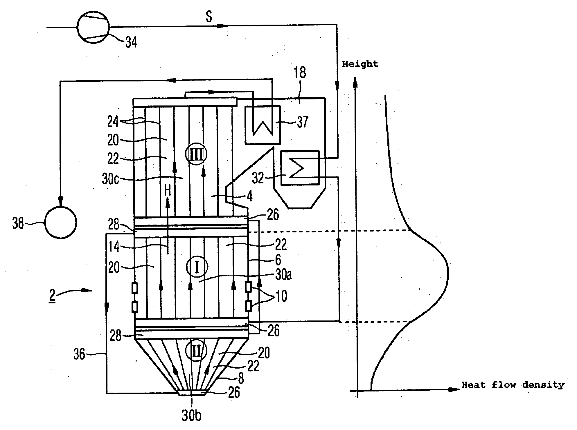
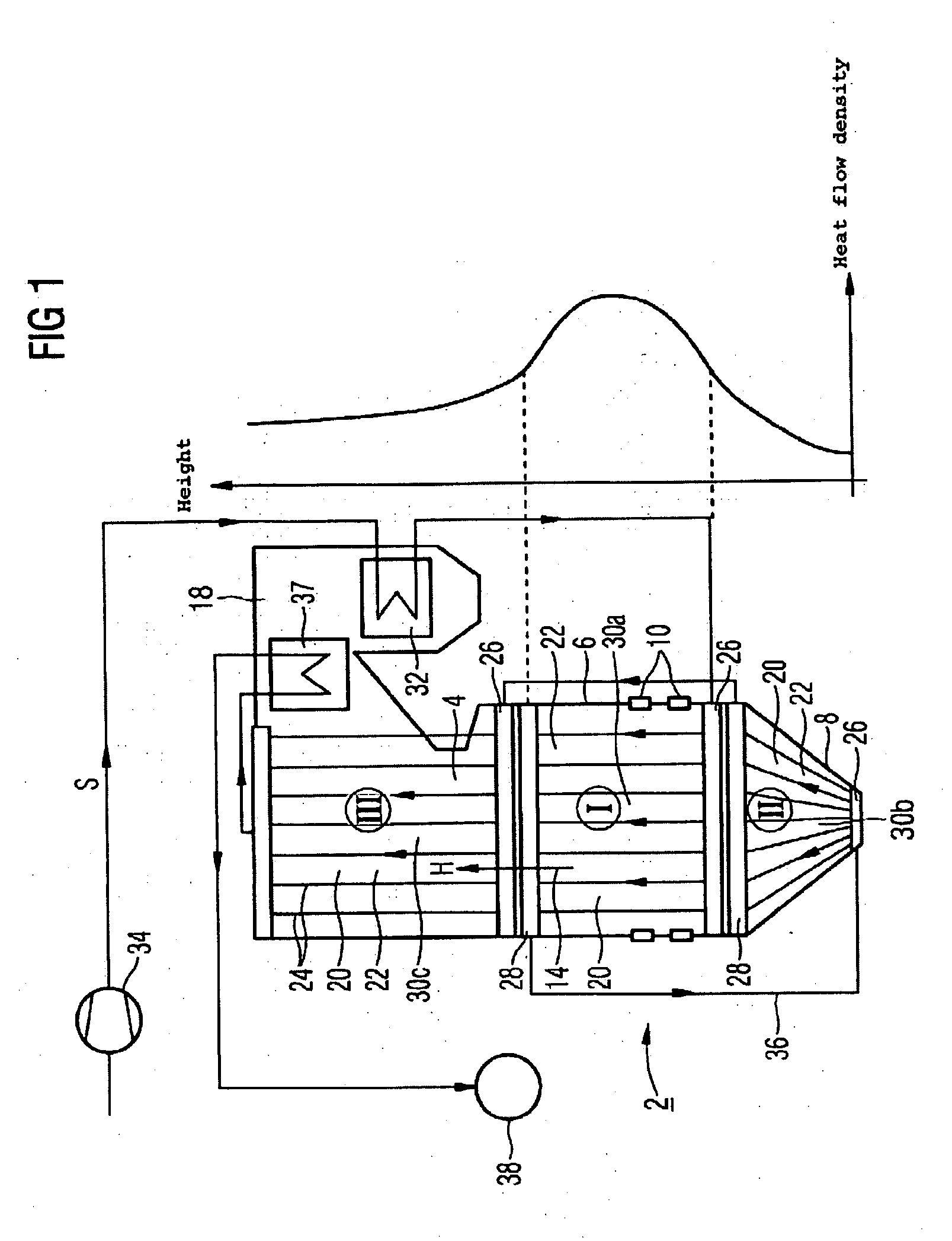
[0035]The fossil-fuel heated steam generator 2 according to the left part of FIG. 1 is conceived as a continuous steam generator with an upright structure. It comprises a combustion chamber 4 with a vertical structure, with a number of combustion chamber walls 6 forming the enclosing wall of the combustion chamber 4. Above a tapering section around the base of the combustion chamber 4 forming a funnel 8, a number of burners 10 are arranged, to which fossil fuel is fed via a fuel line. The hot gas H heated by the flames of the burner 10 flows in an approximately vertical flow direction, shown by the arrow 14, to the outlet opening arranged at the upper end of the combustion chamber 4. After flowing through the connected gas train 18, which in particular comprises a number of superheater heating surfaces 37, the hot gas H, which has in the meantime been cooled to the greatest possible degree, escapes through a chimney (not shown) into the environment. Ash-type combustion residues drop...


PUM


Abstract

The invention relates to a fossil-energy heated continuous steam generator, whereby the at least one combustion chamber, viewed in the flow direction of the hot gases, is divided into at least two throughflow segments, formed by evaporator heating surfaces, whereby the evaporator heating surfaces each comprise steam generation tubes welded to each other in a gastight manner and pressurized in parallel with a flow medium. According to the invention, said generator is suitable for operation with high fresh steam parameters, such as for example, steam temperatures of approximately 700° C., with a simple construction and particularly simple assembly, whereby a throughflow segment, arranged after the first through flow segment, viewed in the direction of flow of the hot gases, forms the first evaporator stage for the flow medium, such that the injection of particularly cold flow medium can occur in the region of maximum heating.

Description

CROSS REFERENCE TO RELATED APPLICATIONS[0001]This application is the US National Stage of International Application No. PCT / EP2005 / 053566, filed Jul. 22, 2005 and claims the benefit thereof. The International Application claims the benefits of German application No. 10 2004 046 187.2 filed Sep. 23, 2004, both of the applications are incorporated by reference herein in their entirety.FIELD OF INVENTION[0002]The invention relates to a fossil-fuel heated continuous steam generator, in which at least one combustion chamber wall of the combustion chamber, viewed in the direction of flow of the hot gas, is divided into at least two throughflow segments formed by evaporator heating surfaces, with the evaporator heating surfaces each comprising steam generator tubes that are welded together in a gas-tight manner in each instance and can each be subjected to the action of a flow medium in a parallel manner.BACKGROUND OF THE INVENTION[0003]In the case of a power plant with a steam generator, ...

Claims


Application Information

Patent Timeline
Patent Type & Authority Applications(United States)
IPC IPC(8): F22B33/00
CPCF22B29/062
Inventor EFFERT, MARTINFRANKE, JOACHIMKRAL, RUDOLF
Owner SIEMENS AG
Why Eureka
Try Eureka