MRI apparatus and RF pulse generating circuit

a pulse generation circuit and rf technology, applied in the direction of instruments, magnetic measurements, measurement devices, etc., can solve the problems of reducing image quality, noise that is easily superimposed on analog magnetic resonance signals, and may be generated, so as to reduce noise

Inactive Publication Date: 2008-10-23
GE MEDICAL SYST GLOBAL TECH CO LLC
View PDF14 Cites 9 Cited by
  • Summary
  • Abstract
  • Description
  • Claims
  • Application Information

AI Technical Summary

Benefits of technology

[0026]Effect of the Invention. As noted above, according to the invention, it is possible to provide an MRI apparatus that can reduce noise that is superimposed on analog magnetic resonance signals from digital RF pulse signals transmitted on a digital bus, and also an RF pulse generating circuit used to generate RF pulses in the MRI apparatus.

Problems solved by technology

When noise is superimposed on analog magnetic resonance signals, the noise appears as an artifact in an image reconstructed by the MRI apparatus and degrades the image quality.
This results in that noise is easily superimposed on analog magnetic resonance signals.
Consequently, noise that is superimposed on analog magnetic resonance signals may be generated from a wiring path through which analog RF pulse signals are sent to the RF coil.
However, weak noise that is superimposed on analog magnetic resonance signals is also generated from a digital bus through which digital RF pulse signals are sent to the D / A converter.

Method used


Image

  • MRI apparatus and RF pulse generating circuit
  • MRI apparatus and RF pulse generating circuit
  • MRI apparatus and RF pulse generating circuit

Examples


Embodiment Construction

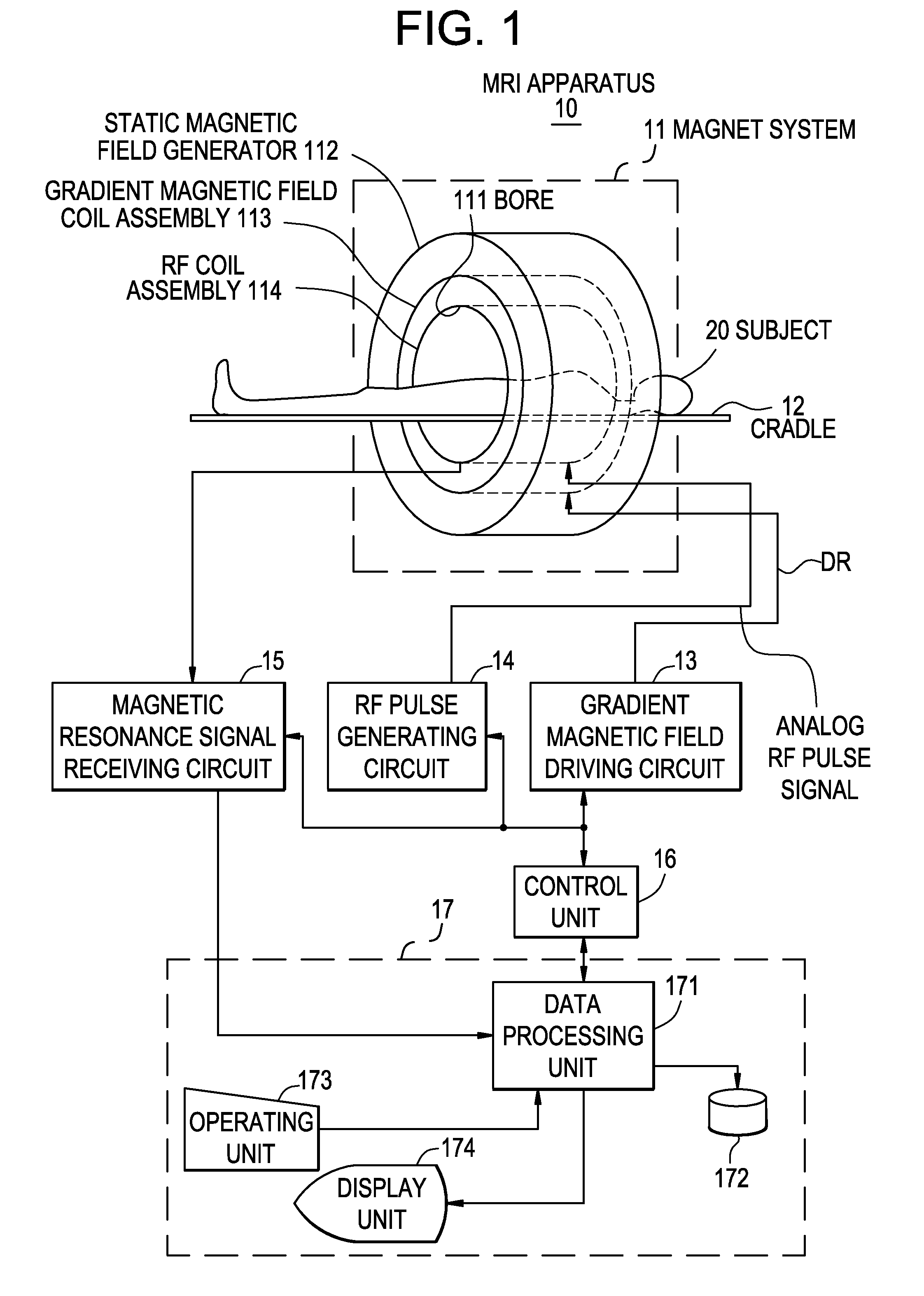
[0036]FIG. 1 is a diagram showing an MRI apparatus. The MRI apparatus 10, as shown in FIG. 1, includes a magnet system 11, a cradle 12, a gradient magnetic field driving circuit 13, an RF pulse generating circuit 14, a magnetic resonance signal receiving circuit 15, a control unit 16, and an operator console 17.

[0037]The magnet system 11 involves a practically transversely-cylindrical internal space (bore) 111, as shown in FIG. 1, and the cradle 12 on which a subject 20 is laid, supported on a cushion, is moved into the bore 111 by a transport mechanism which is not shown.

[0038]In the magnet system 11, around the magnet center of the bore 11 (the scan center position), a static magnetic field generator 112, a gradient magnetic field coil assembly 113, and an RF coil assembly 114 are placed, as shown in FIG. 1.

[0039]The static magnetic field generator 112 forms a static magnetic field in the bore 111. The direction of the static magnetic field is, for example, parallel with the axial...


PUM


Abstract

An MRI apparatus includes: an RF coil to which analog RF pulse signals are applied; an RF pulse generating circuit which generates said analog RF pulse signals; and a magnetic resonance signal receiving circuit which receives analog magnetic resonance signals and converts these signals into baseband digital magnetic resonance signals, said RF pulse generating circuit comprising: a carrier signal generator which generates a digital carrier signal having a predetermined number of bits; a digital modulator which modulates said digital carrier signal with a digital envelope signal, thus generating digital RF pulse signals; a digital-analog converter which converts said digital RF pulse signals into the analog RF pulse signals; and an inversion unit which generates a digital inverted carrier signal having a two's complement relationship with said digital carrier signal and sends the digital inverted carrier signal to said magnetic resonance signal receiving circuit, said magnetic resonance signal receiving circuit comprising: an analog-digital converter which converts the analog magnetic resonance signals into digital magnetic resonance signals having a predetermined number of bits; and a digital demodulator which demodulates said digital magnetic resonance signals with said digital inverted carrier signal, thus converting these signals into the baseband digital magnetic resonance signals.

Description

CROSS REFERENCE TO RELATED APPLICATIONS[0001]This application claims the benefit of Japanese Patent Application No. 2007-109062 filed Apr. 18, 2007.BACKGROUND OF THE INVENTION[0002]The subject matter described herein relates to an MRI apparatus and an RF pulse generating circuits. More specifically, the subject matter described herein relates to an MRI apparatus that can reduce noise introduced when generating RF pulses and an RF pulse generating circuit used to generate RF pulses in the MRI apparatus.[0003]A high precision is required for RF pulse frequency. Therefore, a direct digital synthesizer (hereinafter referred to as a DDS) is used to generate RF pulses in a digital signal form (hereinafter referred to as digital RF pulse signals) and these pulses are converted into RF pulses in an analog signal form (hereinafter referred to as analog RF pulse signals) through a digital-analog converter (hereinafter referred to as a D / A converter). Hereinafter, “RF pulses” mean those that a...

Claims


Application Information

Patent Timeline
IPC IPC(8): G01R33/36
CPCG01R33/3607G01R33/3621
Inventor YOSHIZAWA, NOBUHIRO
Owner GE MEDICAL SYST GLOBAL TECH CO LLC
Why Eureka
Try Eureka