Radar System

a radar and system technology, applied in the field of radar systems, can solve the problems of limited horizontal sensing width, insufficiently meeting the needs of vehicle manufacturers for substantially flatter sensors, and relatively large physical depth, and achieve the effects of optimally flat front ends, high precision of angular separation, and excellent angular separation

Inactive Publication Date: 2008-10-23
ROBERT BOSCH GMBH
View PDF48 Cites 94 Cited by
  • Summary
  • Abstract
  • Description
  • Claims
  • Application Information

AI Technical Summary

Benefits of technology

[0012]The different distance ranges can be switched over flexibly and, if applicable, dynamically. The possibility of using digital evaluation methods means that excellent angular separation can be achieved, in particular by way of parameter estimation methods. This allows reliable sensing of a narrow-lane situation, or separation of closely adjacent and, in some situations, very different vehicles. With the use of planar radiators, in particular patch elements, that are drivable individually or, in particular, in columns, a shallow installation depth can be achieved. The front-end design of the radar system is scalable, i.e. by way of specific embodiments the front end can be adapted to particular requirements, e.g. in terms of location field and range, and can thus be used, for example, at the rear of the vehicle for blind-spot monitoring, lane-change assistance, etc., optionally also with a different configuration of the digital signal evaluation system. The exemplary embodiments and / or exemplary methods of the present invention permits the use of modern evaluation methods whose angular separation capability is not directly correlated with the size of the radiating aperture but, theoretically, is in fact almost independent thereof.
[0013]Methods of this kind have been available since the mid-1980s under the designation “subspace-based parameter estimation methods.” The most important representatives are the MUSIC and ESPRIT methods. These approaches are based on the use of multiple parallel antenna elements on the receiving side, each having identical, mutually overlapping directional characteristics; and on the evaluation, using digital signal processing, of the correlation properties of these quasi-synchronously present parallel received signals. With a sufficient signal-to-noise (S / N) ratio at the receivers, these approaches allow highly precise angular separation even when the objects to be separated have very different reflectivities.
[0014]For the implementation of antenna arrangements of this kind, it is advantageous to use planar antenna structures, such as so-called patch antennas or other planar antenna structures such as dipoles, or short conductor pieces (“stubs”) that are not loaded at the end, which moreover offer the possibility of obtaining maximally flat front ends to minimize overall depth. To achieve maximum horizontal sensing without so-called “grating lobes” with corresponding ambiguities in terms of angle estimation, the parallel individual radiators may have a spacing on the order of half the free-space wavelength, i.e. approx. 2 mm at 77 GHz.
[0015]When parallel arrangements of this kind are used, it is possible to utilize so-called digital beam shaping methods, in which a collimated beam lobe is formed only by digital signal processing, rather than at the analog high-frequency level as in the case of a lens antenna or parabolic antenna. Digital beam shaping is particularly advantageous for the detection of distant objects, since it yields a sufficient S / N ratio and thus enables reliable location.

Problems solved by technology

One limitation of present-day sensors is that the physical depth is relatively large, and vehicle manufacturers' need for substantially flatter sensors can be only insufficiently met.
The restricted horizontal sensing width resulting from the antenna concepts that have been selected is likewise disadvantageous, for example because “cutting-in” vehicles can be detected only at a very late point in time, or relevant objects disappear more often from the “field of view” in sharp curves.
A further substantial limitation may be seen in the fact that while the radar sensors used hitherto can very precisely determine the angular offset of objects in the aforesaid horizontal sensing region (angular accuracy), this is in general reliably possible only if only one object, at a specific distance and at a specific relative velocity, is to be sensed.
This is not acceptable for an ACC sensor, since the maximum permissible overall size is limited to much smaller dimensions.

Method used


Image

  • Radar System
  • Radar System
  • Radar System

Examples


Embodiment Construction

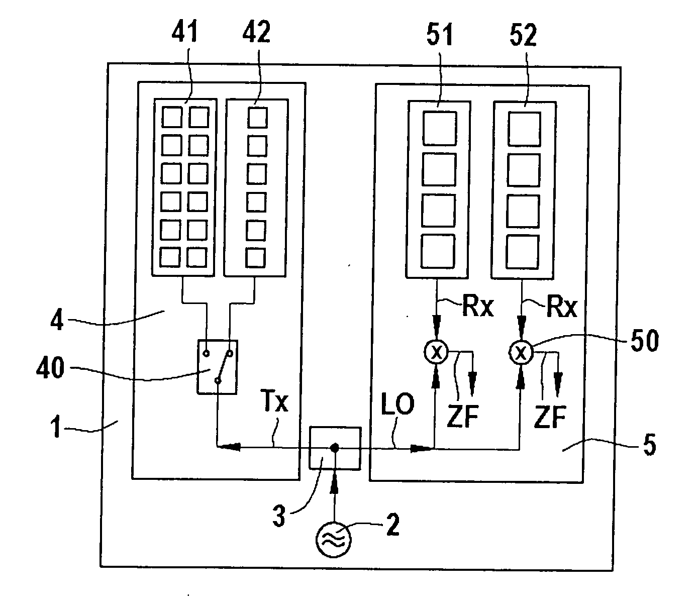
[0033]FIG. 1 is a block diagram of a radar front end 1. This front end 1 is made up specifically of:[0034]a modulatable 77-GHz source 2 (so-called modulated local oscillator), stabilized optionally via a PLL and optionally via a DRO, which may be highly integrated into so-called MMICs;

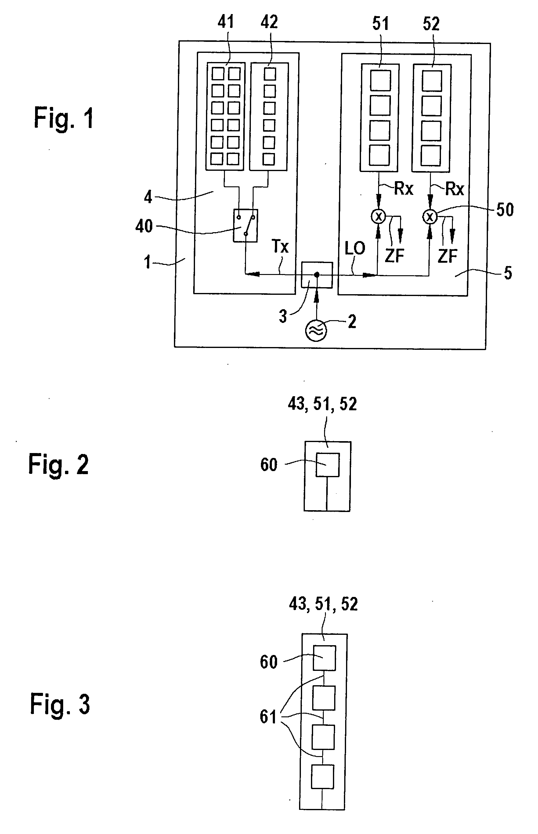
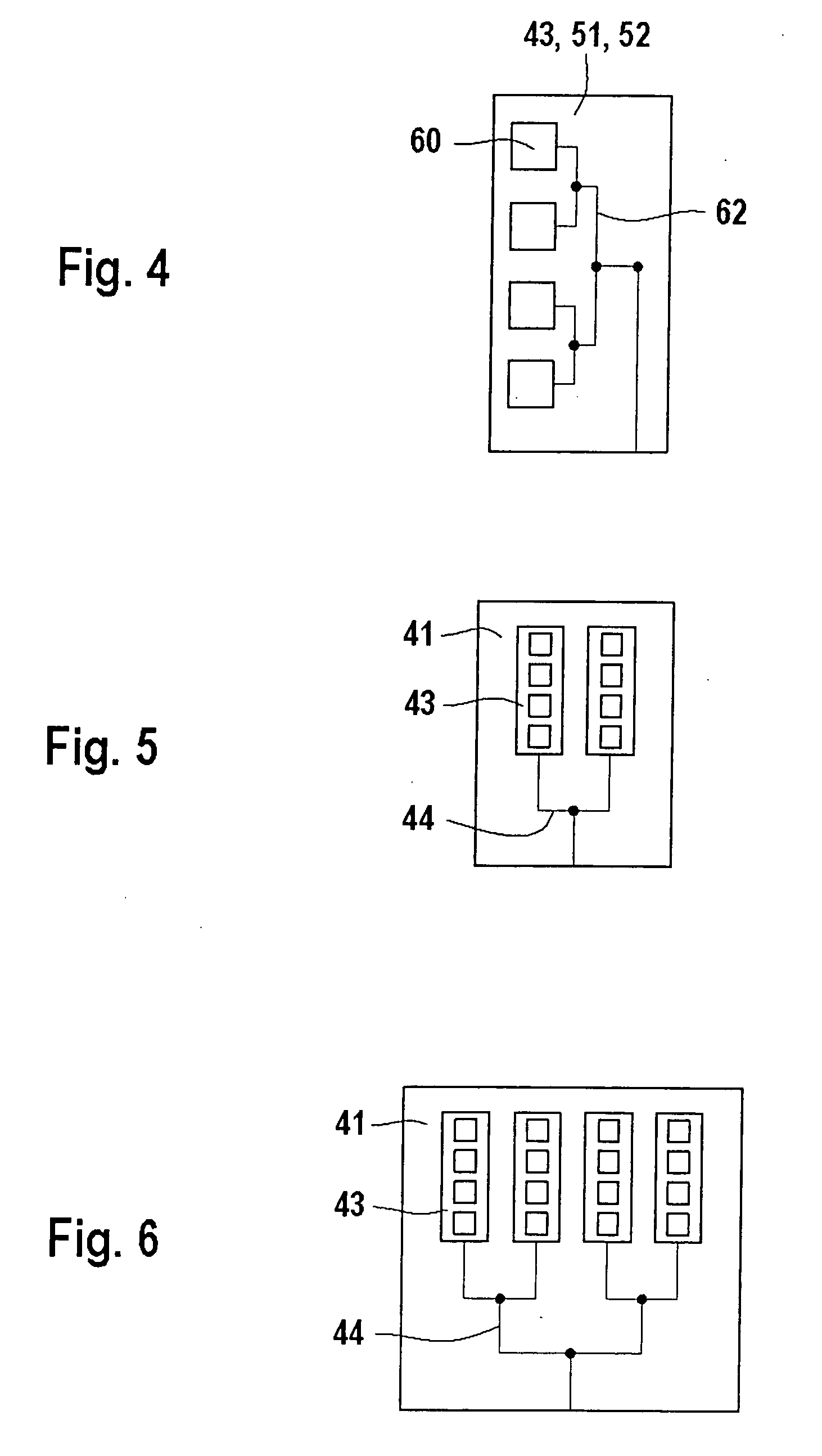
a transmitting unit 4 made up of:[0035]at least two different transmitting antennas 41 and 42 using planar technology (patch antennas), of which one antenna 41 is designed so that by corresponding superimposition of the waves of the individual radiators belonging to antenna 41, it generates a comparatively strongly collimated antenna lobe; a further antenna 42 which is designed so that by corresponding superimposition of the waves of the individual radiators belonging to antenna 42, it generates a comparatively wide azimuthal antenna characteristic, or comprises only one radiator element; optionally further transmitting antennas which are designed so that they generate further specific transmission cha...


PUM


Abstract

In a radar system, a switcher is provided for switching over between at least two different directional characteristics, in particular for different distance ranges, of at least two transmitting antennas. On the receiving side, a combined evaluation of the digitized signals of at least two receiving antennas is performed, in the manner of a correlation of the receiving antenna signals.

Description

FIELD OF THE INVENTION[0001]The present invention concerns a radar system having at least two transmitting antennas having different directional characteristics.BACKGROUND INFORMATION[0002]Radar sensors (primarily in the 76-77 GHz frequency region) have been in use for several years in the field of driver-assistance functions with predictive sensing systems. These sensors are at present still being used in the higher-end sector to implement the “adaptive cruise control” (ACC) assistance function in the 30-180 km / h speed range.[0003]The radar sensors available on the market at present are characterized by the following properties: range of up to approx. 120-150 m[0004]horizontal sensing in the range + / −4°+ / −10°[0005]angular accuracy of approx. 0.5°.[0006]One limitation of present-day sensors is that the physical depth is relatively large, and vehicle manufacturers' need for substantially flatter sensors can be only insufficiently met.[0007]The restricted horizontal sensing width resu...

Claims


Application Information

Patent Timeline
Patent Type & Authority Applications(United States)
IPC IPC(8): G01S13/00G01S13/931
CPCG01S7/032G01S13/44G01S2013/9378H01Q3/24G01S13/931G01S2013/93272
Inventor SCHOEBERL, THOMASFOCKE, THOMASHANSEN, THOMASSCHNEIDER, MARTINSCHOEBEL, JOERGGROSS, VOLKERBRUEGGEMANN, OLIVER
Owner ROBERT BOSCH GMBH
Why Eureka
Try Eureka