Eureka AIR delivers breakthrough ideas for toughest innovation challenges, trusted by R&D personnel around the world.

Independent Positioning Device and Independent Positioning Method

a positioning device and positioning method technology, applied in the field of point positioning apparatus and point positioning method, can solve the problems of not estimating the position with a high accuracy, the estimation process was complicated, and the estimation result could not be so high accuracy, so as to achieve the estimation of the receiver's position and integer ambiguity high accuracy, high accuracy, the effect of high accuracy

Active Publication Date: 2008-10-23
THE RITSUMEIKAN TRUST +1
View PDF5 Cites 25 Cited by
  • Summary
  • Abstract
  • Description
  • Claims
  • Application Information

AI Technical Summary

Benefits of technology

The invention provides a point positioning apparatus and method that can estimate the receiver's position with high accuracy without being affected by the complications of the ionosphere and troposphere. The apparatus includes a satellite data observing device, an ionosphere data getting device, a troposphere data getting device, and a position estimating device. The position estimating device applies a parameter estimation algorithm to a regression equation that includes the explanatory variables and the objective variables. The objective variables include the carrier phases, code pseudoranges, clock errors of the receiver, and the delay data of the ionosphere and troposphere. The apparatus and method set the carrier phases, code pseudoranges, and orbits data of the satellites as the observed values and the clock errors of the receiver and satellites as the unknown values. The invention sets the position of the receiver in three dimensions, the clock error of the receiver, and the integer ambiguity of the carrier waves and satellites as the unknown values. The invention also includes an integer ambiguity estimation method and a state estimation algorithm for the regression equation.

Problems solved by technology

Consequently the estimation result of the positioning varied widely, so we could not estimate the position with a high accuracy.
But this estimation process was complicated, and the estimation result varied more widely under the influence of a threshpassed of noise after a estimation process with the single phase difference.
Despite a complication of the estimation process, the estimation result could not be so high accuracy.
And the complication of the estimation process made a processing speed very slow.

Method used


Image

  • Independent Positioning Device and Independent Positioning Method
  • Independent Positioning Device and Independent Positioning Method
  • Independent Positioning Device and Independent Positioning Method

Examples


Embodiment Construction

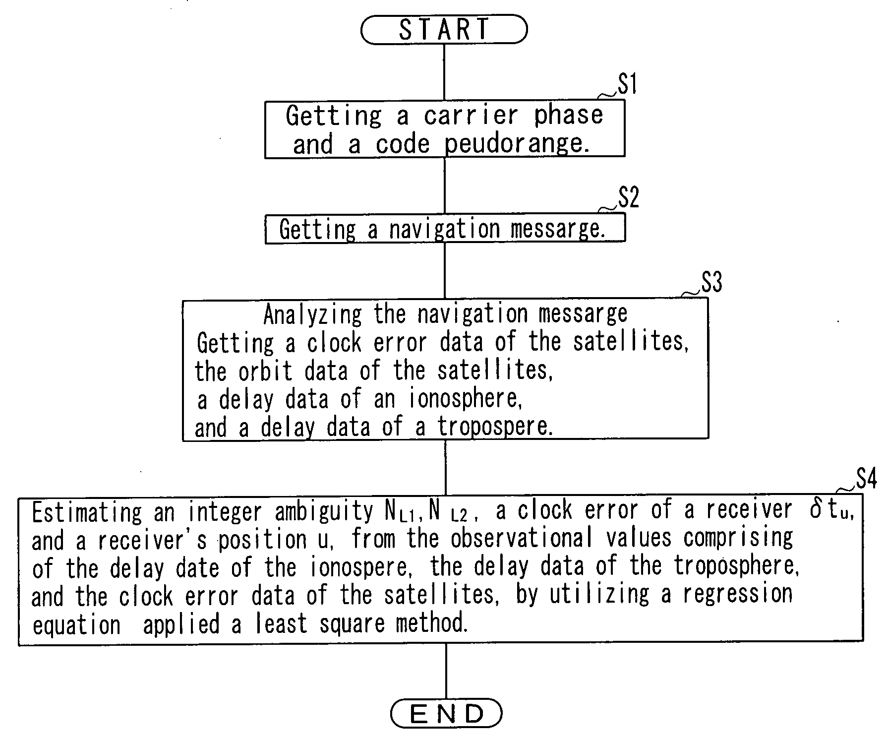
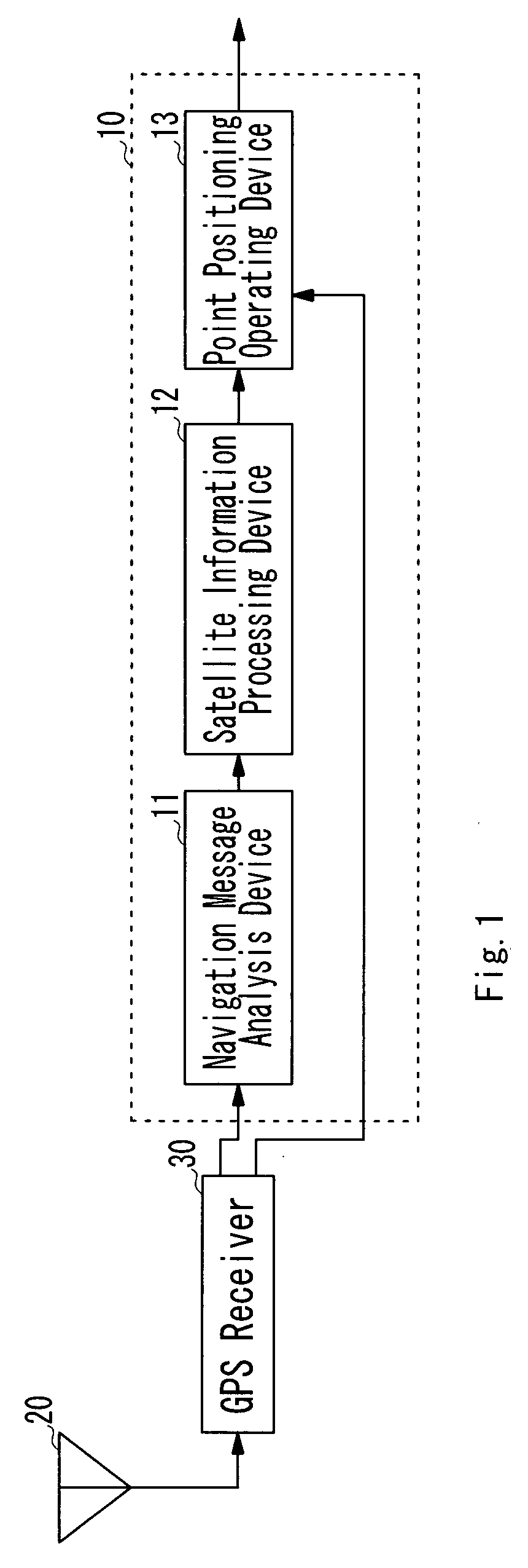
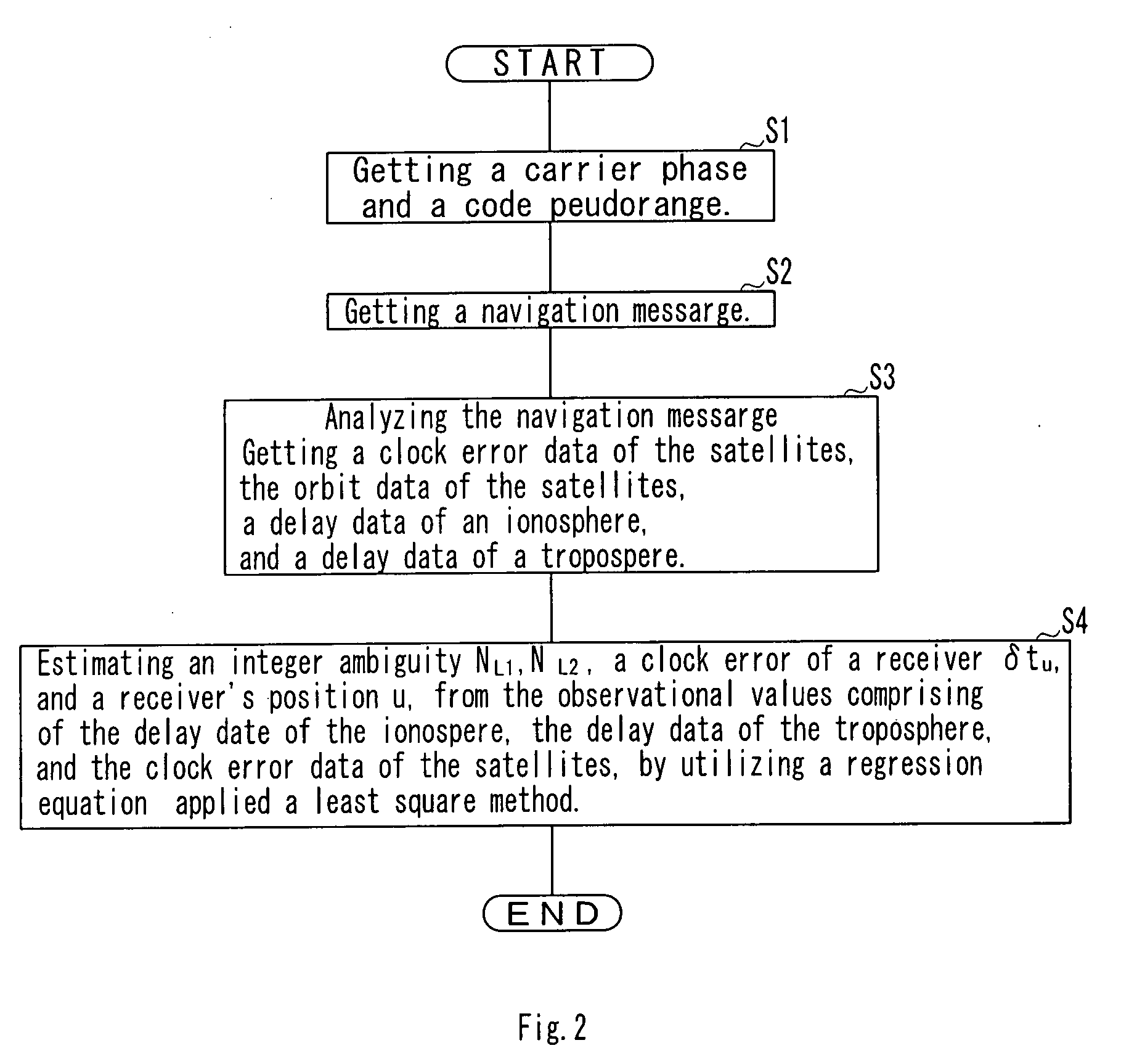
[0032]With reference to the accompanying drawings, an embodiment of the invention which is a point positioning apparatus will be described below. The following explanation of an embodiment explains GPS (Global Positioning System), but can apply to other all GNSS (Global Navigation Satellite System) FIG. 1 is a block diagram illustrating an embodiment of the point positioning apparatus. FIG. 2 is a flowchart illustrating an estimation process of a positioning system composed of the point positioning apparatus and a GPS receiver.

[0033]As shown FIG. 1, the point positioning apparatus connects to the GPS receiver 30, and includes a navigation message analysis device 11, a satellite information processing device 12, and a point position operating device 13.

[0034]The GPS receiver 30 connects to a antenna, and gets a L1 carrier phases, a L2 carrier phases, a pseudorange based on the C / A code, a pseudorange based on the P(Y) code, and a navigation message on L1 carrier by known method from ...


PUM


Abstract

A linear regression equation is comprised of the objective variables and the explanatory variables. The objective variables are comprised of the L1 carrier phases, the L2 carrier phases, the C / A code pseudorange, the P(Y) code pseudorange, the clock error data, the delay data of the ionosphere, and the delay data of the troposphere that related with every satellite respectively. The explanatory variables are comprised of at least the integer ambiguity and a receiver's position.The receiver's position has been linear-approximated by using the estimation results of the passed receiver's positions. Applying a least square method to the regression equation, the integer ambiguity and the receiver's position is estimated.

Description

TECHNICAL FIELD[0001]The invention relates to point positioning apparatus and point positioning method configured to estimate a receiver's position by utilizing the satellite signals transmitted from the satellites.BACKGROUND ART[0002]Various types of a point positioning apparatus and method which estimate the point position utilizing the satellite signals of positioning from the satellites are disclosed. A basic positioning estimation of these apparatus is to introduce a nonlinear simultaneous equation comprising of a code pseudorange, a receiver's position in three dimensions, and a clock error of a receiver. And this estimation applied a Newton method, an extended Kalmann Filter to the nonlinear simultaneous equation. Applying to this estimation, various types of a method to eliminate an influence of an ionosphere and a troposphere are disclosed, too. One method set the delay of the ionosphere and the delay of the troposphere to “0” at initial condition. And the other method esti...

Claims


Application Information

Patent Timeline
Patent Type & Authority Applications(United States)
IPC IPC(8): G01S5/14G01S19/44G01S19/40
CPCG01S19/40G01S19/44G01S19/32G01S19/04
Inventor SUGIMOTO, SUEOKUBO, YUKIHIROKAGAWA, KAZUNORITAJIMA, YASUHIRONAKAMURA, MITSURU
Owner THE RITSUMEIKAN TRUST
Why Eureka
Eureka Blog
Learn More