
Reticle defect inspection apparatus and reticle defect inspection method

a technology of defect inspection and inspection apparatus, applied in the direction of photometry using electric radiation detectors, originals for photomechanical treatment, instruments, etc., can solve problems such as reducing yields in manufacturing processes

Active Publication Date: 2008-10-23
KIOXIA CORP +1
View PDF3 Cites 9 Cited by
  • Summary
  • Abstract
  • Description
  • Claims
  • Application Information

AI Technical Summary

Problems solved by technology

One of major causes for reduced yields in a manufacturing process of such an LSI includes defects contained in a reticle (also called a mask) used when a hyperfine pattern is exposed and transcribed onto a semiconductor wafer using lithography technology.

Method used


Image

  • Reticle defect inspection apparatus and reticle defect inspection method
  • Reticle defect inspection apparatus and reticle defect inspection method
  • Reticle defect inspection apparatus and reticle defect inspection method

Examples


first embodiment

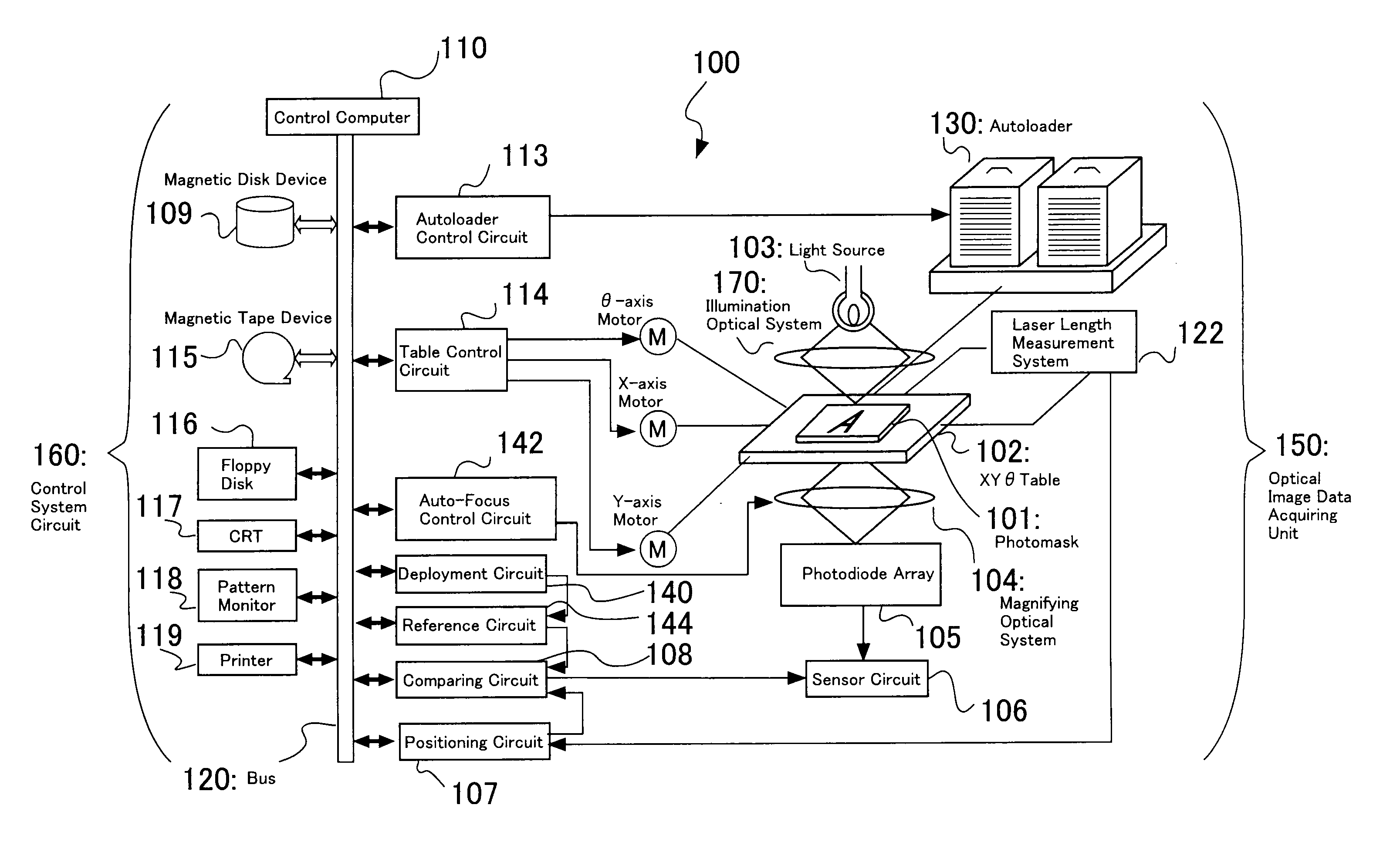
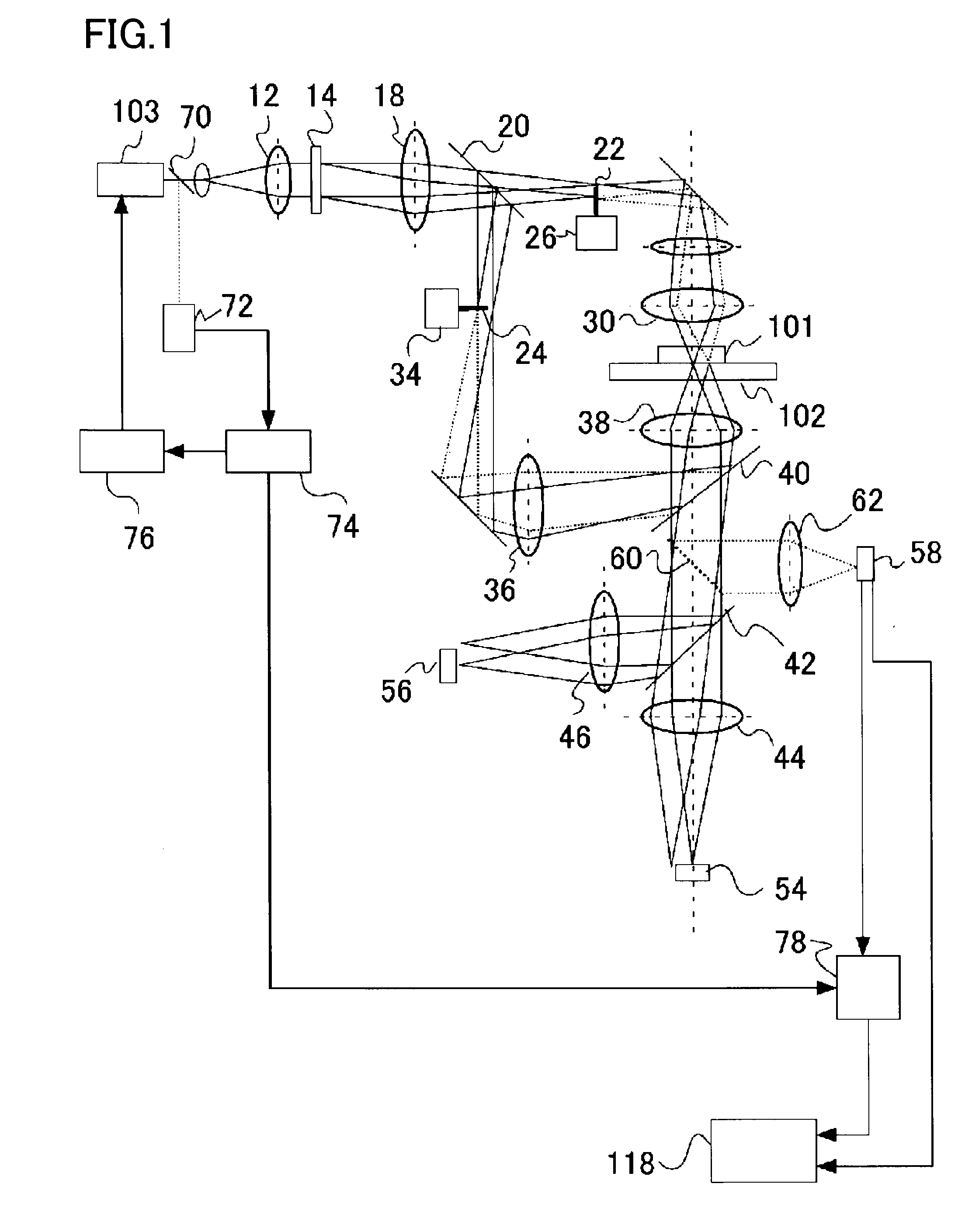
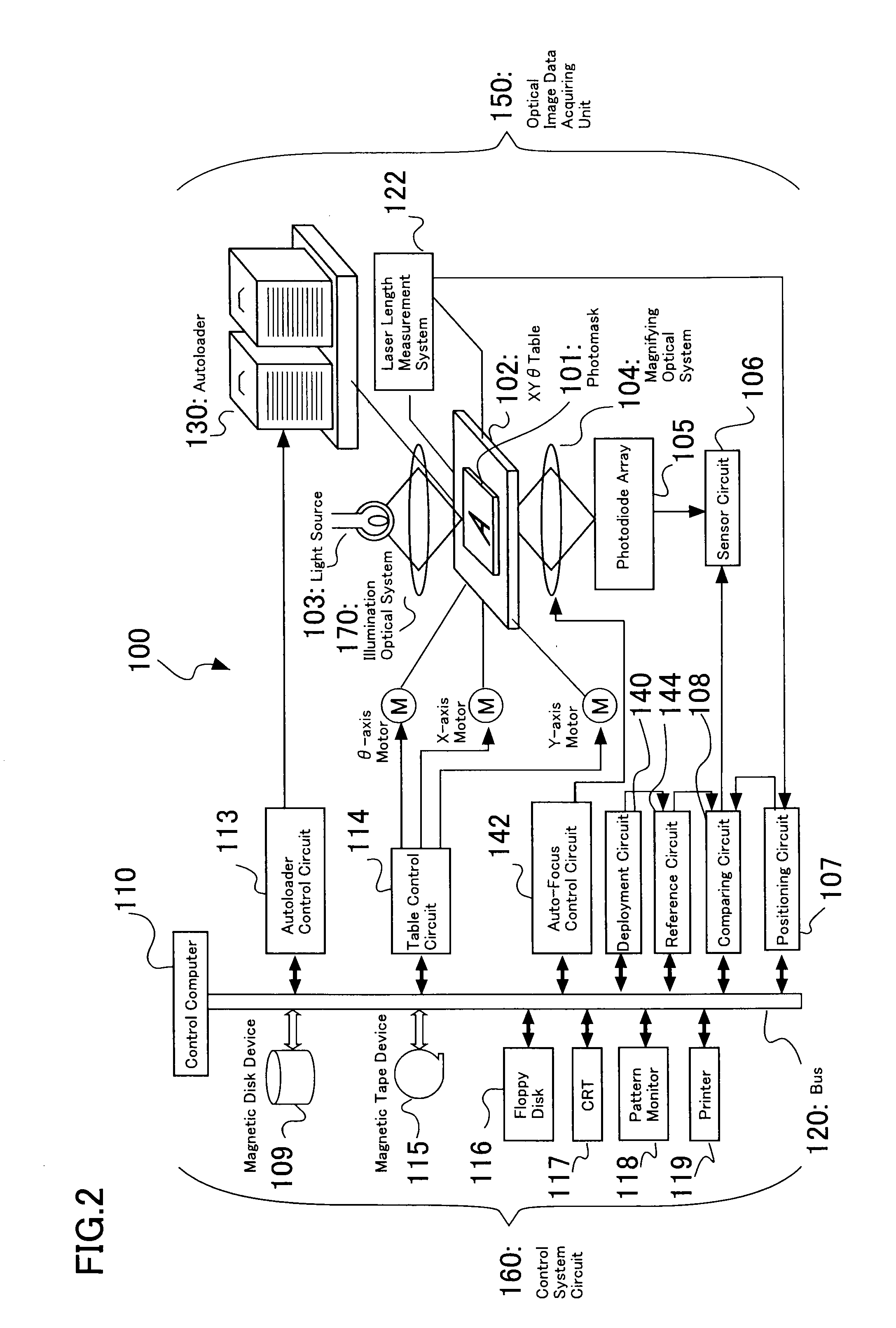
[0017]A reticle defect inspection apparatus according to the present embodiment is a reticle defect inspection apparatus for inspecting for defects on a reticle using a pattern image obtained by irradiating the reticle on which a pattern is formed with light. The reticle defect inspection apparatus includes a dose monitoring part for measuring a dose of the light to the reticle, a comparing part for comparing, after calculating accumulated irradiation from the dose measured by the dose monitoring part, the accumulated irradiation with a preset threshold, and a stop mechanism for stopping irradiation of the reticle with the light when, as a result of the comparison, the accumulated irradiation exceeds the threshold.

[0018]In the present embodiment, a reticle, which is a sample to be inspected by the reticle defect inspection apparatus, is a transmission type reticle for DUV exposure. An inspection apparatus that can perform a simultaneous inspection of transmission and reflection of t...

second embodiment

[0052]A reticle defect inspection apparatus according to the embodiment of the present invention is the same as that in the first embodiment except that the reticle to be a measured sample is a reflection type reticle for EUV exposure and the illuminating optical system consists exclusively of an optical system of reflected illumination and thus, a description thereof is omitted. Also, a reticle defect inspection method in the present embodiment is basically the same as that in the first embodiment except that a reticle for EUV exposure is used and thus, a description thereof is omitted.

[0053]FIG. 4 is a diagram showing principal parts of an optical system and a control system of a reticle defect inspection apparatus in the present embodiment. As shown in FIG. 4, the reticle defect inspection apparatus in the present embodiment has no optical system of transmitted illumination and is configured to perform a reticle inspection exclusively by an optical system of reflected illuminatio...


PUM

PropertyMeasurementUnit
wavelengthaaaaaaaaaa
reticle defect inspectionaaaaaaaaaa

Abstract

A reticle defect inspection apparatus that controls damage of a reticle by irradiation with an inspection light when the reticle is caused to be at rest is provided. The reticle defect inspection apparatus is a reticle defect inspection apparatus for inspecting for defects on a reticle using a pattern image obtained by irradiating the reticle on which a pattern is formed with light. The reticle defect inspection apparatus has a dose monitoring part for measuring a dose of the light to the reticle, a comparing part for comparing, after calculating accumulated irradiation from the dose measured by the dose monitoring part, the accumulated irradiation with a preset threshold, and a stop mechanism for stopping irradiation of the reticle with the light when, as a result of the comparison, the accumulated irradiation exceeds the threshold.

Description

CROSS-REFERENCE TO RELATED APPLICATION[0001]This application is based upon and claims the benefit of priority from Japanese Patent Application No. 2007-109289, filed on Apr. 18, 2007, the entire contents of which are incorporated herein by reference.FIELD OF THE INVENTION[0002]The present invention relates to a reticle defect inspection apparatus and a reticle defect inspection method for performing an inspection using an image obtained by irradiating a sample with light.BACKGROUND OF THE INVENTION[0003]Some patterns constituting a large-scale integrated circuit (LSI), as exemplified by DRAM of a gigabit class, have a minimum design rule reduced from submicron up to the order of nanometer. One of major causes for reduced yields in a manufacturing process of such an LSI includes defects contained in a reticle (also called a mask) used when a hyperfine pattern is exposed and transcribed onto a semiconductor wafer using lithography technology.[0004]With increasingly finer pattern dimen...

Claims


Application Information

Patent Timeline
Patent Type & Authority Applications(United States)
IPC IPC(8): G01J1/46G01N21/956G03F1/24G03F1/84H01L21/027
CPCG01N21/956G01N2021/95676G03F1/84
Inventor HIRANO, RYOICHIOGAWA, RIKI
Owner KIOXIA CORP
Learn More