Disk recording medium, disk drive apparatus, reproducing method, and disk manufacturing method

a technology of disk drive and recording medium, which is applied in the direction of digital signal error detection/correction, recording signal processing, instruments, etc., can solve the problems of inability to write, disadvantageous prerecording method of embossed pits, and difficulty in making groove depth and embossed pit depth different from each other, so as to improve the recording and reproducing operation performance of disk drive apparatus, improve the accuracy, and the effect of easy determination of position

Inactive Publication Date: 2008-10-23
SONY CORP
View PDF7 Cites 0 Cited by
  • Summary
  • Abstract
  • Description
  • Claims
  • Application Information

AI Technical Summary

Benefits of technology

[0022]This eliminates the need for recording the prerecorded information by embossed pits. Since it is not necessary to form embossed pits, the depth of the groove can be reduced. That is, the depth of the groove can be set to an optimum state for high-density recording without regard for reproduction characteristics of the embossed pits. Thus high-density recording that realizes a capacity of 23 GB or the like on a disk 12 cm in diameter, for example, is made possible.
[0034]Thus, the present invention is suitable for a large-capacity disk recording medium, and great effects are obtained in that the disk drive apparatus is improved in recording and reproducing operation performance and the wobble processing circuit system may be a simple one.

Problems solved by technology

The dye film change recording method is also referred to as a write-once recording method, which allows data recording only once and does not allow rewriting.
Considering high-density recording and reproduction on an optical disk, however, the method of prerecording by embossed pits is disadvantageous.
In the case of a disk having a groove and embossed pits produced simultaneously by a stamper, it is very difficult to make depth of the groove and depth of the embossed pits different from each other.
However, when the depth of the embossed pits is reduced, a signal of good quality cannot be obtained from the embossed pits.
After all, a good solution as a common depth of the groove and the embossed pits has not been obtained.

Method used


Image

  • Disk recording medium, disk drive apparatus, reproducing method, and disk manufacturing method
  • Disk recording medium, disk drive apparatus, reproducing method, and disk manufacturing method
  • Disk recording medium, disk drive apparatus, reproducing method, and disk manufacturing method

Examples


Embodiment Construction

[0060]An optical disk according to an embodiment of the present invention will hereinafter be described, and also a disk drive apparatus (recording and reproducing apparatus) and a manufacturing method provided for the optical disk will be described in the following order.

[0061]1. Disk

[0062]1-1. Physical Characteristics of Optical Disk

[0063]1-2. Prerecorded Information

[0064]1-3. ADIP Address

[0065]2. Disk Drive Apparatus

[0066]3. Disk Manufacturing Method

1. Disk

1-1. Physical Characteristics of Optical Disk

[0067]Physical characteristics of a disk according to the embodiment and a wobbling track will first be described.

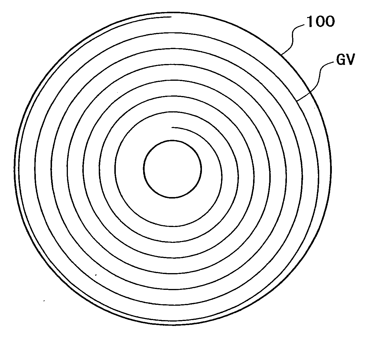
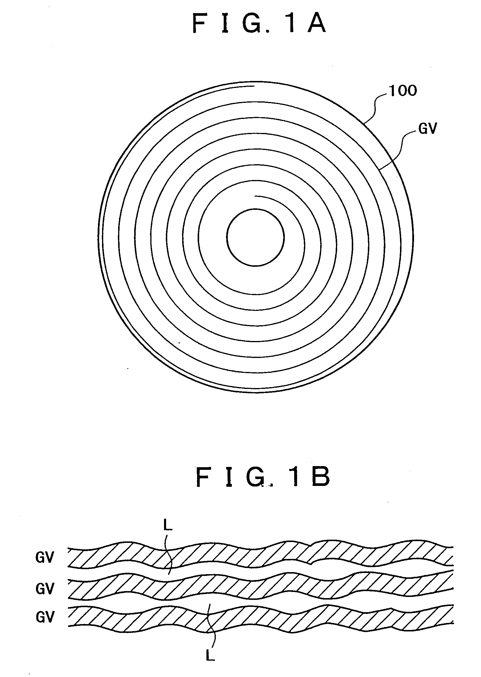
[0068]The optical disk in this example belongs to a category of disks recently developed under a name of DVR (Data&Video Recording) disks, for example, and particularly has a new wobbling system as a DVR system.

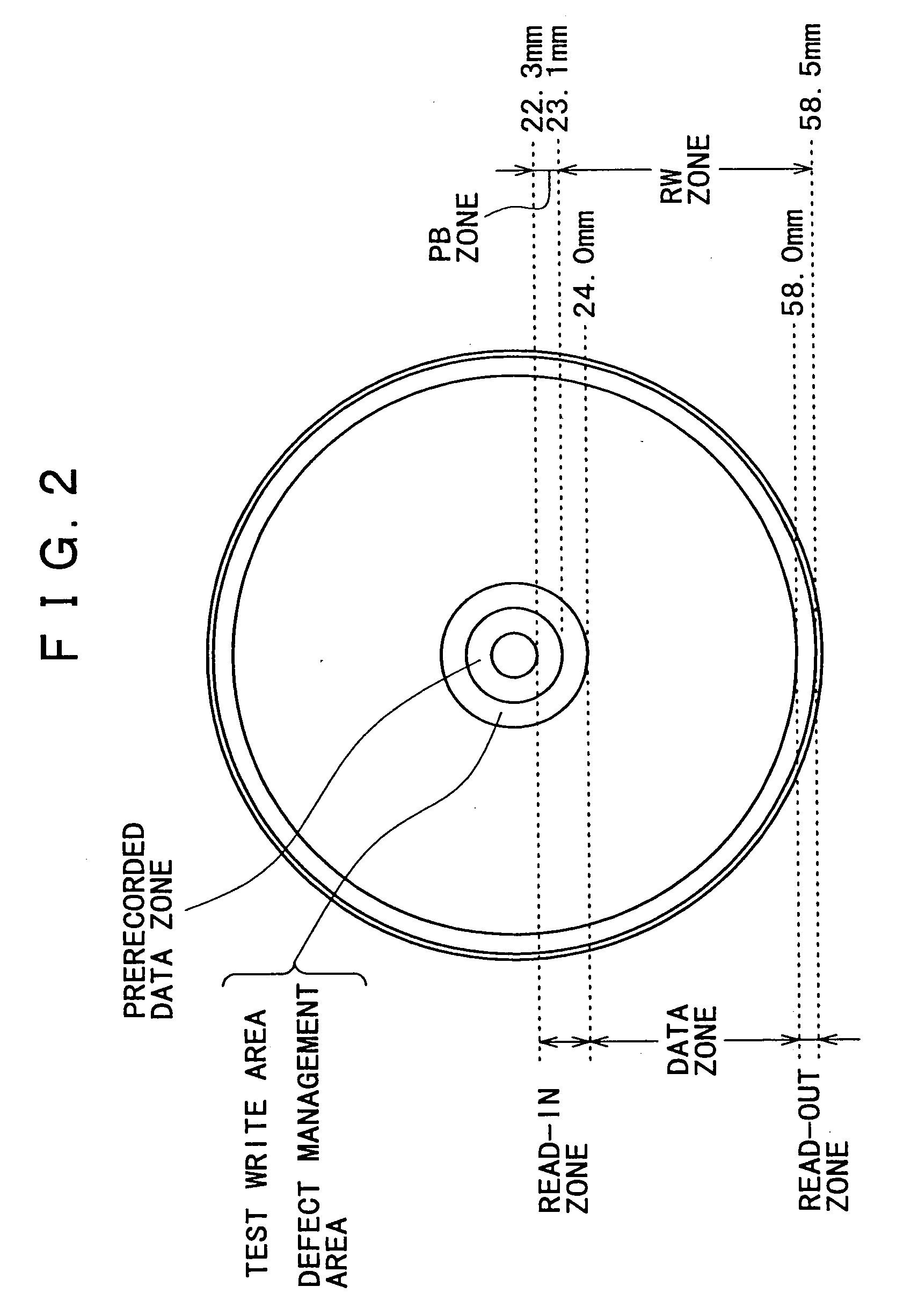
[0069]Data is recorded on the optical disk in this example by a phase change method. As to disk size, the optical disk is 120 mm in diameter. The optical disk has ...


PUM

PropertyMeasurementUnit
thicknessaaaaaaaaaa
thicknessaaaaaaaaaa
diameteraaaaaaaaaa

Abstract

A recording and reproducing area and a reproduction-only area are formed by wobbling a groove formed in a spiral fashion to form a track to be tracked on a disk. The recording and reproducing area has address information recorded by wobbling of the groove and information recorded and reproduced by phase change marks on the track formed by the groove where the address information is recorded. The reproduction-only area has prerecorded information recorded by wobbling of the groove.

Description

CROSS-REFERENCE TO RELATED APPLICATION[0001]This application is a continuation application of U.S. application Ser. No. 10 / 433,756, filed on May 21, 2004, which is a National Stage application of PCT / JP02 / 10373, filed on Oct. 4, 2002, and claims priority to Japanese Patent Application No 2001-311489, filed on Oct. 9, 2001. The entire contents of the above-identified applications are incorporated herein by reference.TECHNICAL FIELD[0002]The present invention relates to a disk recording medium such as an optical disk or the like, a disk manufacturing method for manufacturing the disk recording medium, and a disk drive apparatus and a reproducing method for the disk recording medium, and particularly to a disk having a track wobbled as a pregroove.BACKGROUND ART[0003]As technology for recording and reproducing digital data, there is a data recording technology using optical disks (including magneto-optical disks) such for example as CD (Compact Disk), MD (Mini-Disk), and DVD (Digital V...

Claims


Application Information

Patent Timeline
Patent Type & Authority Applications(United States)
IPC IPC(8): G11B7/24G11B7/005G11B7/007G11B7/24035G11B7/24082G11B7/26G11B7/30G11B20/10G11B20/12G11B20/14G11B20/18G11B20/22G11B27/19G11B27/24
CPCG11B7/0053G11B7/00736G11B7/24082G11B7/261G11B20/00086G11B20/00601G11B20/1217G11B20/1419G11B20/1833G11B20/22G11B27/24G11B2020/1269G11B2020/1272G11B2020/1287G11B2020/1288G11B2020/1836G11B2020/1846G11B2220/216G11B2220/218G11B2220/2529G11B2220/2541G11B2220/2545G11B2220/2562G11B2220/2575G11B7/007
Inventor KOBAYASHI, SHOEI
Owner SONY CORP
Why Eureka
Try Eureka