Pipette for use with a pipette tip or syringe having a piston and a cylinder

a technology of a pipette and a piston, which is applied in the direction of fluid controllers, instruments, laboratory glassware, etc., can solve the problems of pipette contamination by aerosols, pipette metering errors, and difficult pipette pipetting of highly viscous liquids with a positive displacement pipette having a spring apparatus for the upward displacement of the lifting rod, etc., to achieve simple operation, less complex, and more space saving

Pending Publication Date: 2021-12-23
EPPENDORF SE
View PDF2 Cites 0 Cited by
  • Summary
  • Abstract
  • Description
  • Claims
  • Application Information

AI Technical Summary

Benefits of technology

[0011]The object of the invention is to provide a pipette for use with a pipette tip or syringe having a piston and a cylind

Problems solved by technology

Metering errors are a drawback in air-cushion pipettes, due to changes in the length of the air-cushion as a result of the weight of the aspirated liquid and due to changes in the temperature, the air pressure and the air humidity.
A contamination of the pipette by aerosols may also be problematic.
The pipetting of highly viscous liquids with a positive displacement pipette having a spring apparatus for the upward displaceme

Method used


Image

  • Pipette for use with a pipette tip or syringe having a piston and a cylinder
  • Pipette for use with a pipette tip or syringe having a piston and a cylinder
  • Pipette for use with a pipette tip or syringe having a piston and a cylinder

Examples


Embodiment Construction

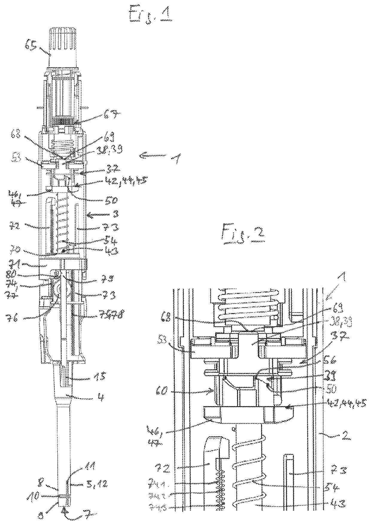
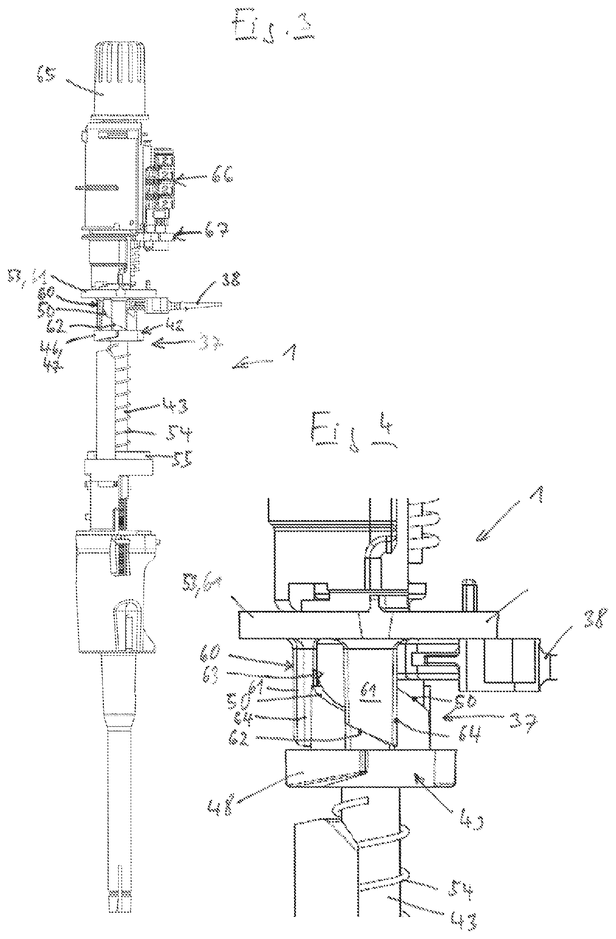
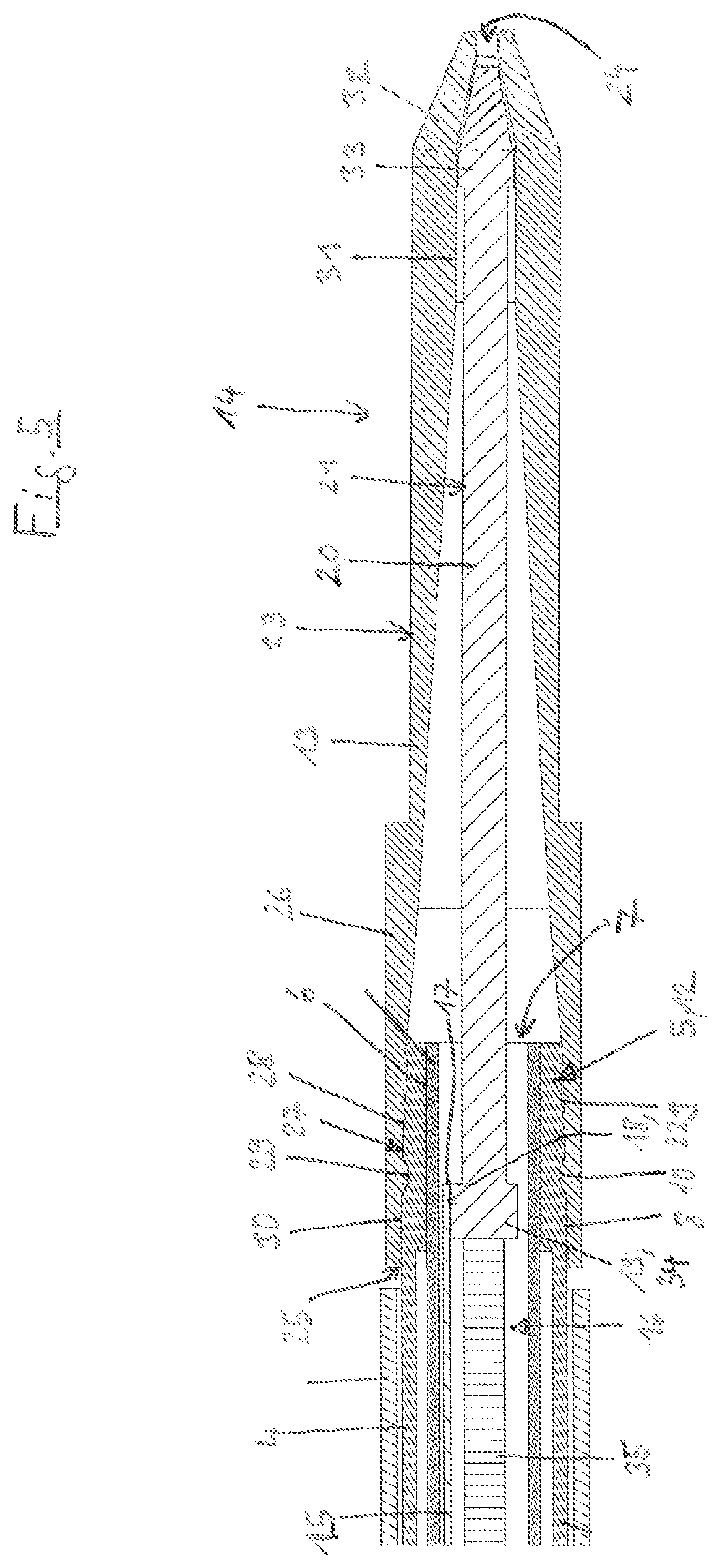
[0059]FIGS. 1 to 5 show an embodiment of a pipette 1 which is configured as a positive displacement pipette and which has a stem-shaped (for example cylindrical) pipette housing 2 which is shown in FIG. 2 in partial view. A chassis 3, on which different components of the pipette 1 are retained, is arranged in the pipette housing 2. A hollow cylindrical shaft 4 protrudes downwardly from the lower end of the pipette housing 2. A neck 5 which has a through-bore 6 with a through-hole 7 at the lower end protrudes downwardly from the lower end of the shaft 4.

[0060]According to FIG. 5, the neck 5 comprises an upper neck portion 8 having the shape of a hollow cylinder and therebelow a lower neck portion 9 having the shape of a hollow sphere. An annular groove 10 circulates on the outer periphery of the neck 5 between the upper neck portion 8 and the lower neck portion 9. From the lower end of the neck 5 two diametrically opposing slots 11 extend beyond the annular groove 10 along the neck 5...


PUM


Abstract

A pipette for use with a pipette, tip or syringe, including a piston positioned within a cylinder comprises a pipette housing extending between an upper end and a lower end. Two parallel rods are positioned in the pipette housing, wherein one of the two parallel rods is coupled to a lifting rod. An operating element is configured to protrude outwardly from the pipette housing and be displaced relative to the pipette housing. A gear mechanism is arranged in the pipette housing and comprises a drive comprising a moveable input member and configured to be driven by the operating element, and an output comprising at least one moveable output member and configured to drive the two parallel rods. Successive displacements of the input member by the operating element are configured to alternately displace one of the two parallel rods and then another of the two parallel rods by the output member.

Description

CROSS REFERENCE TO RELATED INVENTION[0001]This application is based upon and claims priority to, under relevant sections of 35 U.S.C. § 119, European Patent Application No. 20181406.8, filed Jun. 22, 2020, the entire contents of which are hereby incorporated by reference.FIELD OF TECHNOLOGY[0002]This disclosure relates to a pipette for use with a pipette tip or syringe having a piston and a cylinder.BACKGROUND[0003]Pipettes are used, in particular, in scientific and industrial laboratories with medical, molecular biological and pharmaceutical applications for metering selected volumes of liquids. The liquids may be, in particular, homogenous (single-phase) liquids consisting of a single liquid component or a homogenous mixture of a plurality of liquid components (solutions). The liquids may also be heterogeneous (multi-phase) mixtures of a liquid with a further liquid (emulsions) or a solid (suspension).[0004]Known pipettes for use with a pipette tip have a stem-shaped pipette housi...

Claims


Application Information

Patent Timeline
IPC IPC(8): B01L3/02G01N35/10
CPCB01L3/0227B01L3/0282B01L2200/087B01L2400/0478B01L2200/0605G01N35/1011B01L3/0217B01L3/0275
Inventor KUNSCH, MATTHIAS
Owner EPPENDORF SE
Why Eureka
Try Eureka