
Apparatus and method incorporating an indicator chamber for elevated temperature pressure vessel or weld testing

Inactive Publication Date: 2008-10-23
WARDLAW LOUIS J
View PDF4 Cites 0 Cited by
  • Summary
  • Abstract
  • Description
  • Claims
  • Application Information

AI Technical Summary

Benefits of technology

[0014]The present disclosure is directed to a system and process for verifying the integrity of welds or other connection points in the assembly or testing of pressure vessels, at elevated temperatures. When used herein, and, particularly, in the appended claims, “weld” or “welds” is intended to include connection points or means for two or more conduits, pipes, or components of a flange or pressure vessel. The system comprises a source of pressurized gas. An indicator chamber in a housing is provided, the housing having upstream and downstream ends. Means are defined within the chamber housing between the housing ends for receipt of an indicator composition impregnated onto a surface within the chamber. A first conduit is connected between the source of the pressurized gas and the upstream end of the housing for introducing the gas through the conduit and into the chamber and across the removable sur

Problems solved by technology

Consequently, a tremendous amount of preheating is required to obtain a quality weld.
Preheating is often a problem, particularly for drilling rigs located at sea.
This is difficult and time consuming.
While a number of apparatus have been developed for preheating the casing and wellhead to welding temperatures, relatively little has been done in the area of testing or proving the integrity of the welds.
When drilling an oil well, tremendous pressures may be encountered requiring that all connections or welds be leak-proof.
Rapid cooling can damage the metallurgy of the casing and wellhead material.
This procedure is very time consuming and in the event that flaws in the weld are located, the wellhead and casing must be reheated to the welding temperature to repair the flaws or cracks located in the initial welds.
However, in recent years, Freon and other chlorine-containing halogenic gaseous substances have been prohibited as refrigerants and other commercialized uses by many nations in the world because of the belief that it destroys the protective ozone belt in the atmosphere.
Other nations have, however, either not barred use of such gases or have not restricted their use to such a point that they cannot be used in very limited amounts for some uses.
Several other gas compositions have been suggested for many commercial applications, but their overall use and acceptance has been slow due to several disadvantages, not the least of which is the corrosive side effect that some of the newer gas compositions may have when exposed to some exotic metals sometimes found in industrialized applications.
In addition to problems associated with the use of chlorine-containing halogenic gases, any type of marker composition that is desired to be carried with an inert gas, such as nitrogen, has, prior hereto, been required to be provided in bottles or similar transportable containers which, in cases in which the weld to be tested is on an offshore well head, must be transported by boat to the particular work location.
The transport of such bottles is costly, time consuming, and their stacking and storage on the platform or similar work location takes up valuable space.

Method used


Image

  • Apparatus and method incorporating an indicator chamber for elevated temperature pressure vessel or weld testing
  • Apparatus and method incorporating an indicator chamber for elevated temperature pressure vessel or weld testing

Examples


Embodiment Construction

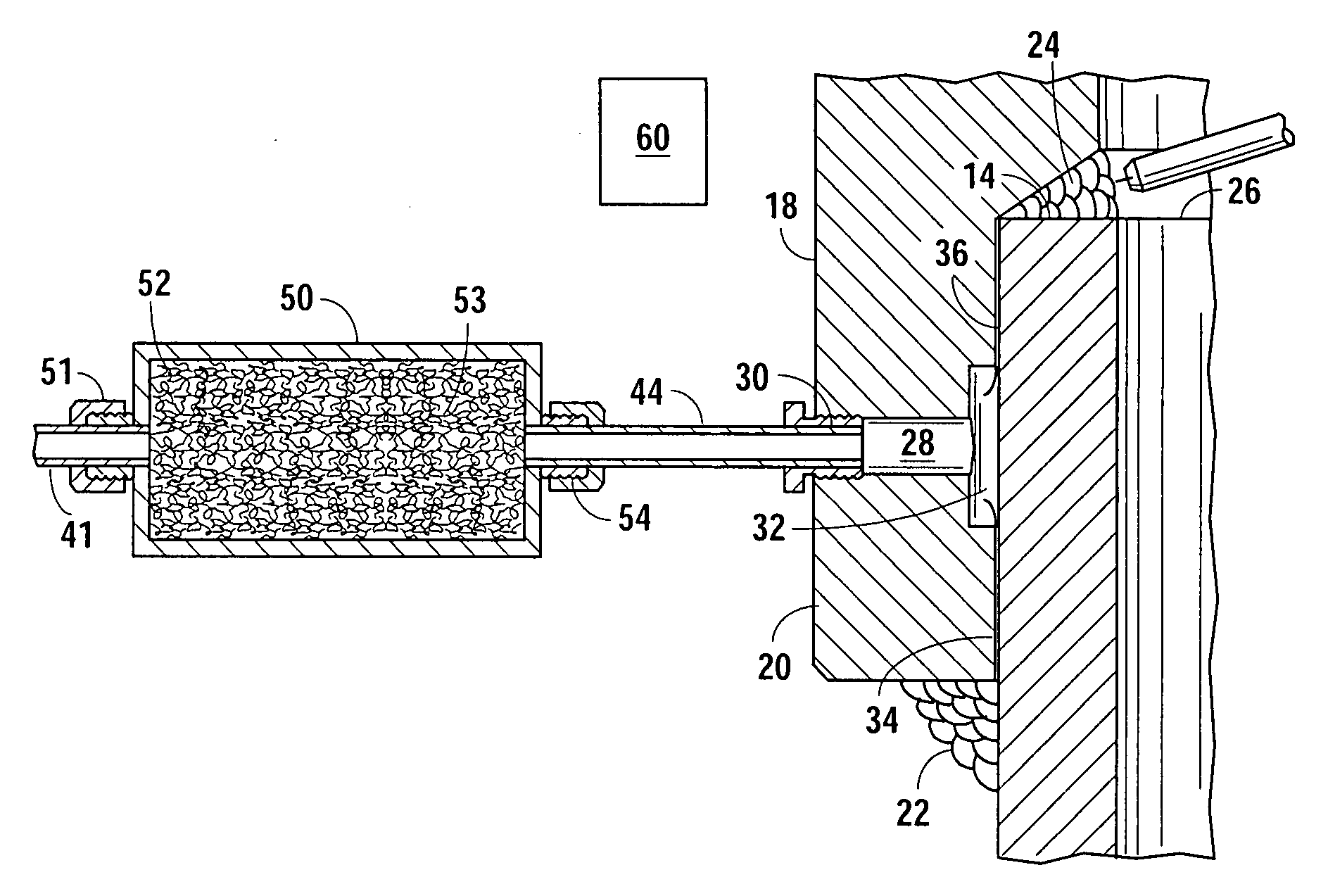
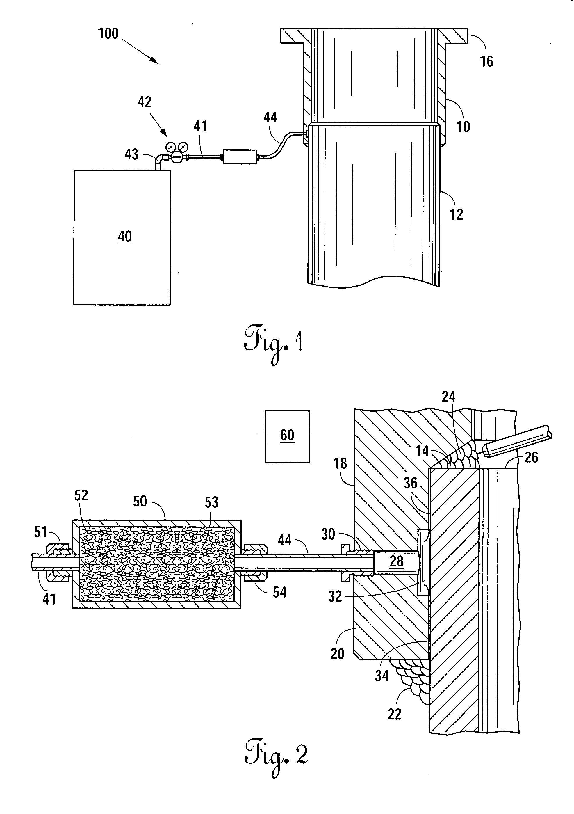
[0017]Attention is first directed to FIG. 1 of the drawings, which shows the general configuration of the system 100 for verifying the integrity of the welds connecting a wellhead or terminal flange 10 to a casing 12.

[0018]Assume, for purposes of illustration, that the casing 12 is a large diameter casing having a wall thickness conforming with industry standards. The casing 12 can range from ½ inch thick to about 1½ inch or greater. The wellhead 10 is connected to the casing 12. The wellhead 10 is constructed with an internal shoulder 14 (FIG. 2) to abut the end of the casing 12.

[0019]The wellhead 10 is generally cylindrical and open at each end. A peripheral, outwardly extending flange 16 is provided about the upper end of the wellhead 10 for connection to other equipment.

[0020]As shown in FIG. 2, at the opposite end of the wellhead 10, a cylindrical portion 18 extends from the shoulder 14 which telescopes over the end of the casing 12. The end or edge of the cylindrical portion 1...


PUM


Abstract

In a method and system for testing the integrity of pressure vessels, or welds on flanges or the like, at elevated temperatures, a pressurized mixture of a gaseous environmentally safe composition is formed within an indicator chamber in a housing receiving a pressurized gas and containing a surface in the chamber upon which is placed an indicator composition including a marker component, whereby the marker component is carried by the carrier gas from within the chamber and through a conduit to the pressure vessel or weld area. The carrier gas and the indicator or marker component are injected in an area between the inner and outer weld of a terminal flange welded to a tubular pipe section or casing. The pressurized composition includes a marker component or sub-composition which is detected by a detection apparatus which scans the pressure vessel area to be tested, or weld area. The pressure of the gas may also be monitored to observe losses in pressure indicative of flaws in the pressure vessel area or welds. The integrity of the pressure vessel or welds is tested at elevated temperature permitting remedial repairs to be made without reheating the work area of the pressure vessel or on a tubular pipe or casing.

Description

BACKGROUND OF THE DISCLOSURE[0001](1) Field of the Invention[0002]This invention is directed to a method for testing the integrity of welds, or welded or other connections in a pressure vessel, and particularly, a process for pressure testing the integrity of such connections or welds at elevated temperatures using a pressurized gas composition formed within an indicator chamber wherein an inert gas is introduced to come into contact with and carry a marker component of an indicator composition, to locate flaws which may be present in the pressure vessel or welds.[0003](2) Brief Description of the Prior Art[0004]In drilling an oil well, it is often necessary to install wellheads of various sizes of large diameter pipe. Several sizes of pipe or casing may be installed in a well. The well might include, as an example, a 36 inch driver pipe. There may also be a 20 inch casing, 13 and ⅜ inch casing and 9 and ⅝ inch casing. It is necessary to install a terminate flange or wellhead at eve...

Claims


Application Information

Patent Timeline
IPC IPC(8): G01N25/72
CPCG01N25/72
Inventor WARDLAW, LOUIS J.
Owner WARDLAW LOUIS J
Learn More