Method and system for drift correction of spectrum images

a spectrum image and drift correction technology, applied in image enhancement, calibration apparatus, instruments, etc., can solve the problems of drift correction vector application after, not widely used, spatial smearing of features, etc., and achieve the effect of simplifying transfer, storage and subsequent processing

Active Publication Date: 2008-10-23
KEYSIGHT TECH
View PDF14 Cites 9 Cited by
  • Summary
  • Abstract
  • Description
  • Claims
  • Application Information

AI Technical Summary

Benefits of technology

[0015]As may be appreciated from the foregoing discussion concurrent collection treats all signal sources as events, allowing the collection of spectral events to be concurrent with the collection of electron events. The events are structured into packets of information that greatly simplifies transfer, storage and subsequent processing for display or analysis. The structuring of events also provides a temporal component that allows processing elements to “look ahead” in the event stream in order to make decisions on how to process up coming events. This “look ahead” capability allows the drift correction vectors to be pre-computed before the x-ray events are inserted into x, y pixel locations, resulting in exact registration. As every frame contains electron image information, the collection process is continuous without the need to stop and collect drift correction-images. In addition, since all event information is saved, drift correction can be applied during or after the spectrum image is collected. Advanced image processing can even detect and skip corrupted frames where the image has been distorted due to electron beam fluctuation or mechanical vibration.

Problems solved by technology

This drift is detrimental to the collection of a spectrum image as it results in a spatial smearing of features.
This procedure is known as passive drift correction and is not widely in use due to the disadvantage of requiring long collection times per pixel in collecting the sequential spectrum image.
It has the disadvantage of requiring that the collected image area be a sub-region of the available field of view.
The largest disadvantage is that the drift correction vectors are applied after drift has been detected.

Method used


Image

  • Method and system for drift correction of spectrum images
  • Method and system for drift correction of spectrum images
  • Method and system for drift correction of spectrum images

Examples


Embodiment Construction

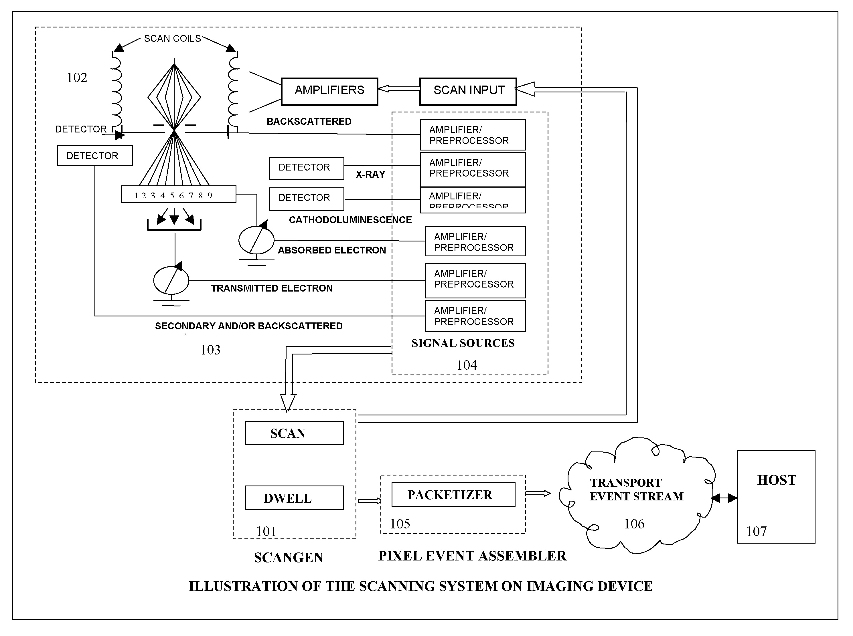
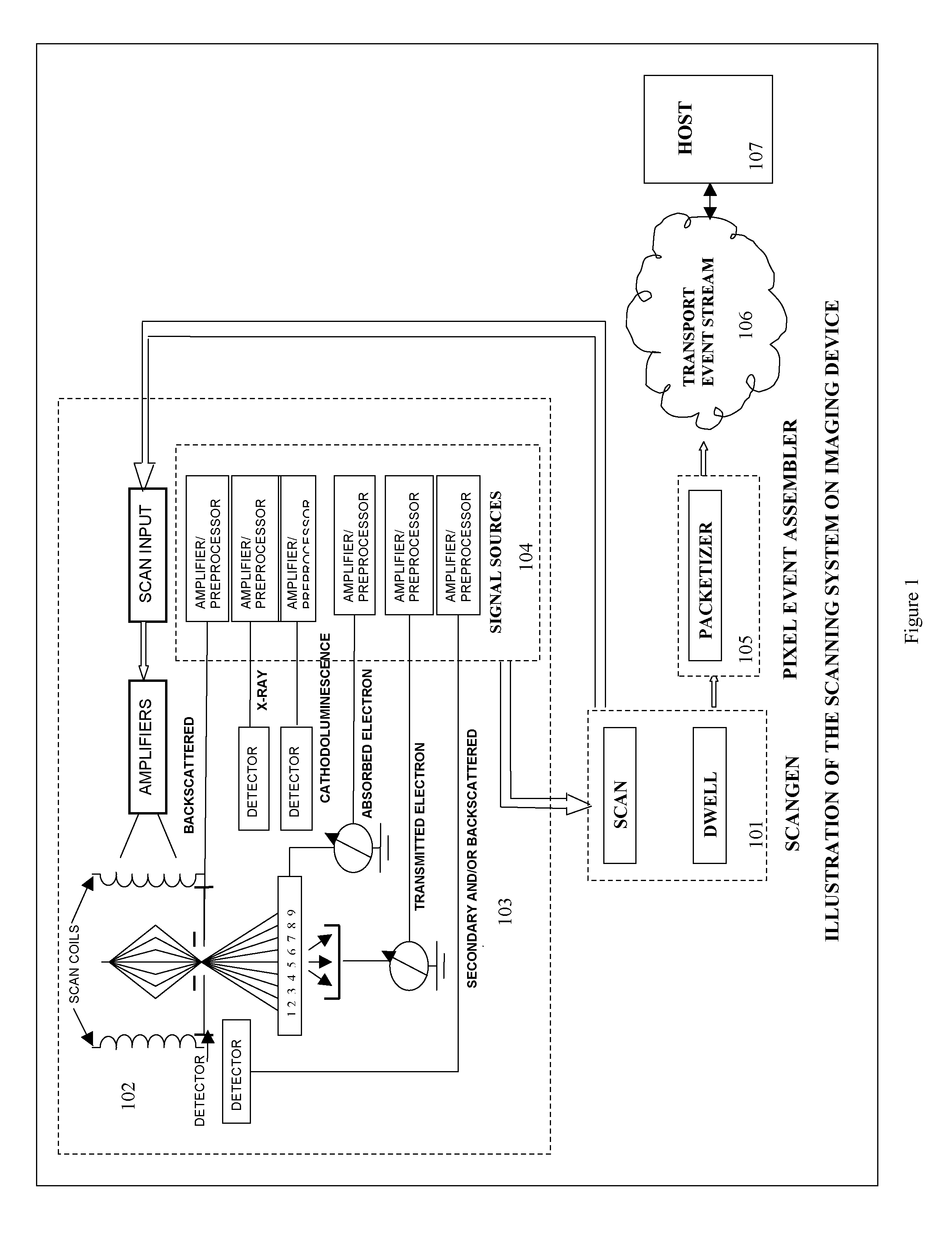
[0020]This invention of drift correction of spectrum images uses a system of concurrent collection of signals from electron and x-ray sources and the treatment of these signals as pixel events. FIG. 1 is a high level block diagram of such a system. A scan generator 101 generates an x, y raster which is used drive scan coils 102 that moves excitation source (electron, ion or photon) over a sample. Such a sample can be, for example, a integrated circuit wafer for the purpose of manufacturing defect analysis. Various electron, photon and x-ray detectors 103 collect signals which are registered to the x, y pixel positions of the beam on the sample. The scan generator 101 acquires data concurrently from all signal sources 104 for every pixel position over the area of interest creating pixel events. A pixel event contains all information related to a pixel position. Each x, y raster over the sample constitutes one frame of pixel events. Pixel events are formatted into packets 105 and stre...


PUM


Abstract

A method and system corrects for drift in spectrum images resulting from collection signals. Signals resulting from a scan are collected. A reference image is obtained for determining initial pixel locations. A correction image is extracted, validated and correction vectors generated.

Description

CROSS-REFERENCE TO RELATED APPLICATIONS[0001]This application is related to and claims priority to Provisional Application Ser. No. 60 / 925,825 filed Apr. 23, 2007, and entitled “Method and System for Drift Correction of Spectrum Images.” The disclosure of said Provisional Application Ser. No. 60 / 925,825 is expressly incorporated by reference herein.BACKGROUND OF THE INVENTION[0002]1. Field of Invention[0003]This invention relates to a method and system for the drift correction of spectrum images. More particularly, this invention describes a method and system for drift correction of spectrum images using concurrent collection signals, for example, both electron and x-ray signals, while eliminating periodic correction-image collection and correction steps.[0004]2. Discussion of Prior Art[0005]Spectrum Imaging is the collection and spatial registration of all spectral events, yielding a spectral data cube. Spectral Events are the converted x-ray energies from an x-ray detector / pulse p...

Claims


Application Information

Patent Timeline
Patent Type & Authority Applications(United States)
IPC IPC(8): G01D18/00
CPCG01J3/28G06T5/50G06T2207/10116
Inventor DAVILLA, SCOTT D.
Owner KEYSIGHT TECH
Why Eureka
Try Eureka