
Dual-Microphone Spatial Noise Suppression

a dual-microphone and spatial noise technology, applied in the field of acoustics, can solve the problems of not being physically desired, the directional gain that can be achieved by only two acoustic pressure microphones is limited to first-, and the reverberation and noise of the room are typical problems, so as to achieve the suppression of acoustic noise in speech, the suppression of off-axis signals is higher, and the added directional gain is small.

Active Publication Date: 2008-10-23
MH ACOUSTICS
View PDF26 Cites 219 Cited by
  • Summary
  • Abstract
  • Description
  • Claims
  • Application Information

AI Technical Summary

Benefits of technology

"The present invention relates to a technique for improving the quality of audio signals collected from microphones on a mobile device. The invention uses a spatial noise suppression (SNS) algorithm that uses a parametric estimation of the main signal direction to attain higher suppression of off-axis signals than is possible by classical linear beamforming for two-element broadside arrays. The SNS algorithm utilizes the power ratio of the two microphone signals to estimate when a desired source is operational and when the input is diffuse noise or directional noise from directions off of broadside. The invention can attain higher levels of noise suppression for off-axis acoustic noise sources than standard optimal linear processing. The technical effects of the invention include improved quality of audio signals collected from microphones on a mobile device."

Problems solved by technology

It is well known that room reverberation and noise are typical problems when using microphones mounted on laptop or desktop computers that are not close to the talker's mouth.
Unfortunately, the directional gain that can be attained by the use of only two acoustic pressure microphones is limited to first-order differential patterns, which have a maximum gain of 6 dB in diffuse noise fields.
This spacing might not be physically desired, or one may desire to extend the spatial filtering performance of a single endfire directional microphone by using an array mounted on the display top edge of a laptop PC.
Similar to the laptop PC application is the problem of noise pickup by mobile cell phones and other portable communication devices such as communication headsets.

Method used


Image

  • Dual-Microphone Spatial Noise Suppression
  • Dual-Microphone Spatial Noise Suppression
  • Dual-Microphone Spatial Noise Suppression

Examples


Embodiment Construction

Derivation

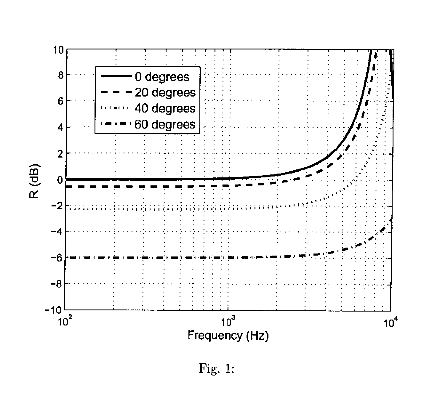
[0028]To begin, assume that two nondirectional microphones are spaced a distance of d meters apart. The magnitude array response S of the array formed by summing the two microphone signals is given by Equation (1) as follows:

S(ω,θ)=2cos(kdcos(θ)2),(1)

where k=ω / c is the wavenumber, ω is the angular frequency, and c is the speed of sound (m / s), and θ is defined as the angle relative to the array axis. If the two elements are subtracted, then the array magnitude response D can be written as Equation (2) as follows:

D(ω,θ)=2sin(kdcos(θ)2).(2)

[0029]An important design feature that can impact the design of any beamformer design is that both of these functions are periodic in frequency. This periodic phenomenon is also referred to as spatial aliasing in beamforming literature. In order to remove frequency ambiguity, the distance d between the microphones is typically chosen so that there is no aliasing up to the highest operating frequency. The constraint that occurs here is that ...


PUM


Abstract

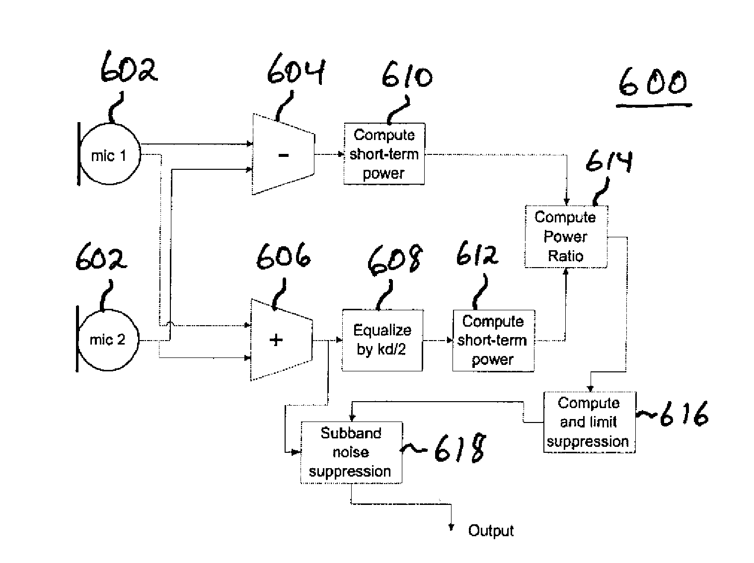
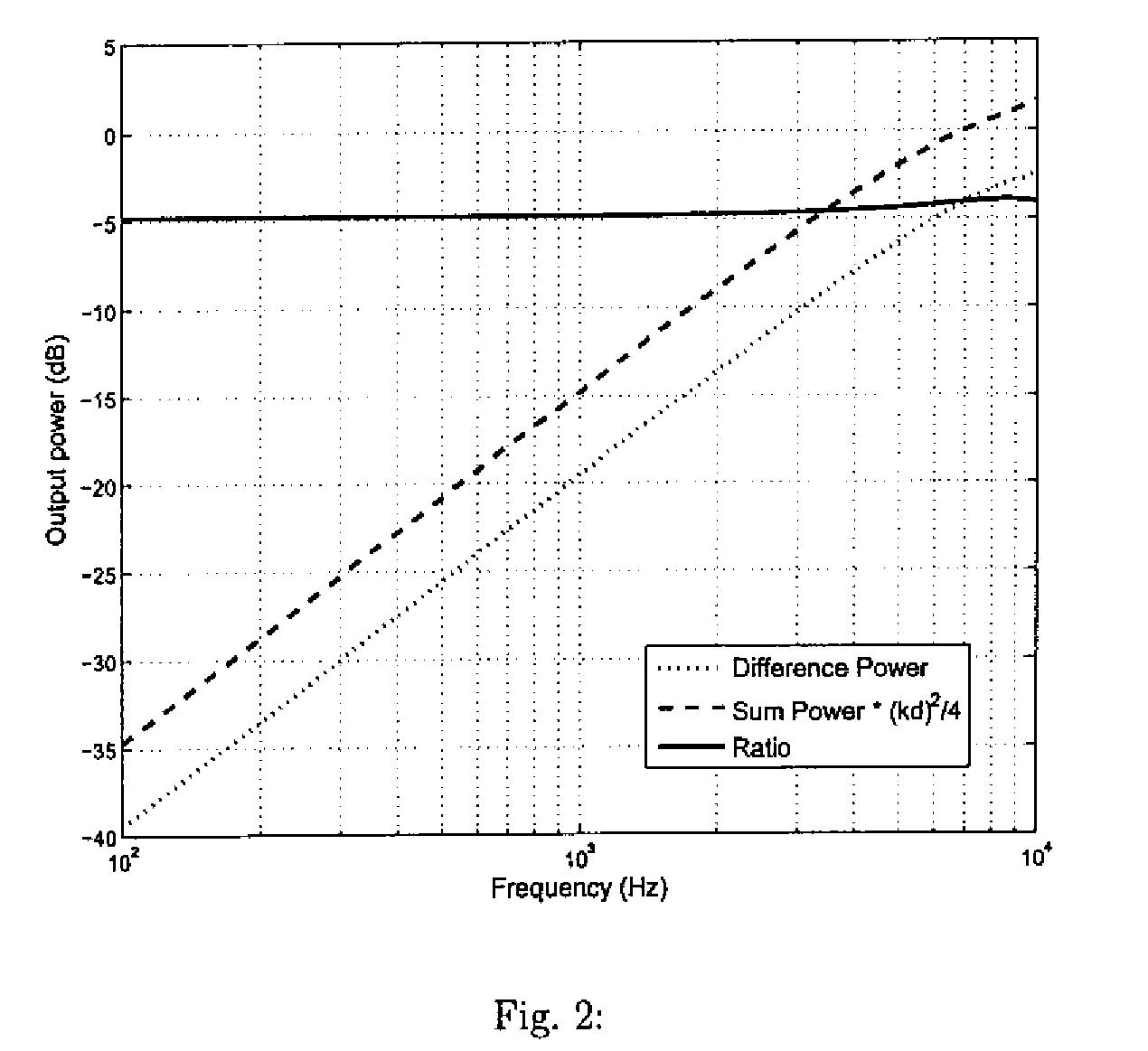
Spatial noise suppression for audio signals involves generating a ratio of powers of difference and sum signals of audio signals from two microphones and then performing noise suppression processing, e.g., on the sum signal where the suppression is limited based on the power ratio. In certain embodiments, at least one of the signal powers is filtered (e.g., the sum signal power is equalized) prior to generating the power ratio. In a subband implementation, sum and difference signal powers and corresponding the power ratio are generated for different audio signal subbands, and the noise suppression processing is performed independently for each different subband based on the corresponding subband power ratio, where the amount of suppression is derived independently for each subband from the corresponding subband power ratio. In an adaptive filtering implementation, at least one of the audio signals can be adaptively filtered to allow for array self-calibration and modal-angle variability.

Description

CROSS-REFERENCE TO RELATED APPLICATIONS[0001]This application is a continuation-in-part of U.S. patent application Ser. No. 10 / 193,825, filed on Jul. 12, 2002 as attorney docket no. 1053.002, which claimed the benefit of the filing date of U.S. provisional application No. 60 / 354,650, filed on Feb. 5, 2002 as attorney docket no. 1053.002PROV, the teachings of both of which are incorporated herein by reference. This application also claims the benefit of the filing date of U.S. provisional application No. 60 / 737,577, filed on Nov. 17, 2005 as attorney docket no. 1053.006PROV, the teachings of which are incorporated herein by reference.BACKGROUND OF THE INVENTION[0002]1. Field of the Invention[0003]The present invention relates to acoustics, and, in particular, to techniques for reducing room reverberation and noise in microphone systems, such as those in laptop computers, cell phones, and other mobile communication devices.[0004]2. Description of the Related Art[0005]Interest in simpl...

Claims


Application Information

Patent Timeline
Patent Type & Authority Applications(United States)
IPC IPC(8): H04R3/00
CPCH04R3/005H04R25/405H04R25/407H04R2410/07
Inventor ELKO, GARY W.
Owner MH ACOUSTICS
Learn More