
Imaging detecting with automated sensing of an object or characteristic of that object

a technology of automatic sensing and object detection, applied in the field of automatic sensing of objects or objects, can solve the problems of background clutter and images of other objects, interfering with the detection of projectiles or characteristics, and limited image processing at the focal plane array of sensors, and achieve the effect of light weigh

Active Publication Date: 2015-01-06
CYAN SYST
View PDF5 Cites 13 Cited by
  • Summary
  • Abstract
  • Description
  • Claims
  • Application Information

AI Technical Summary

Benefits of technology

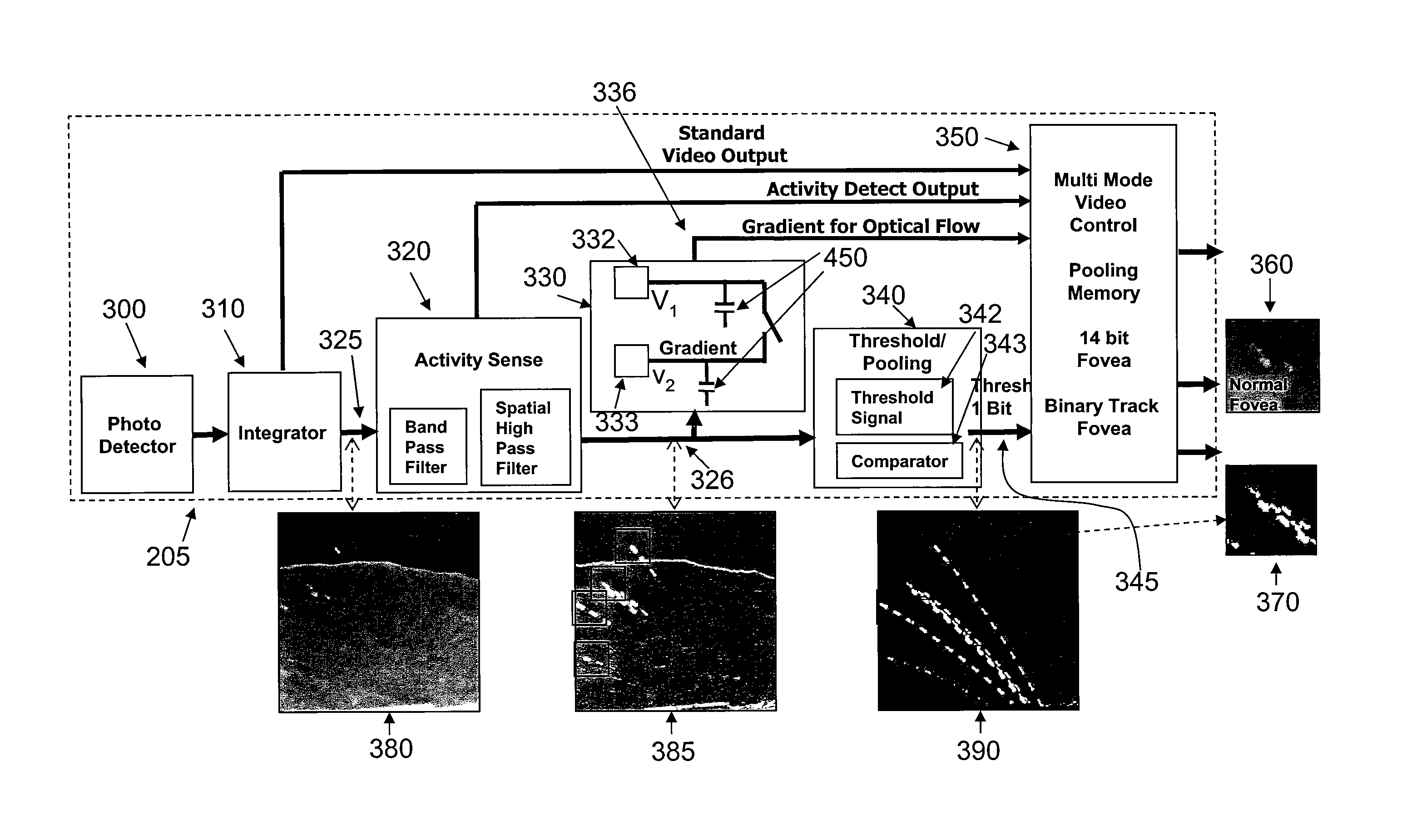
The present invention is about a small and portable imaging system that can detect and extract information from a large number of simultaneous signals in a field environment. The system uses analog processing, charge sharing, and thresholding to achieve target detection and can discriminate between narrow or wide dynamic characteristics. The invention offers compactness, efficiency, and improvements in size reduction, power, and weight, while performing on-site processing that used to require off-image processing.

Problems solved by technology

One of the primary problems in detection of target data within an image and generated by an integrated circuit is that background clutter and images of other objects or characteristics of these other objects appear in a scene.
Again, as a simple example, if one was trying to determine the source of a projectile, and an automobile was moving in proximity to the site of the projectile source, a processing apparatus and method would generate images from those automobile signals, thereby interfering with the detection of the projectile or a characteristic, such as a trajectory, and hence location of a source of the projectile.
In the past, only a limited amount of image processing could have been performed at the focal plane array of sensors.
However, processing was limited and the problem of excess noise was typically quite large in the prior art devices.
The downstream noise in a signal path oftentimes materially interfered in the attempts to determine an activity at an image scene.
Moreover, digital signal processing designers avoided focal plan array processing because of the significantly high cost involved.
In addition to the foregoing, in the prior art image sensors, battery life was relatively short due to the amount power required for any efficient operation of the image sensor and processor.
Moreover, weight was also another factor, particularly where the image sensor and support electronics had to be transported manually.
Often times, the size of the image sensor equipment substantially reduced its functionality.
Furthermore, these systems were not sufficiently light in weight and small and compact so that they could be transported in a field environment.

Method used


Image

  • Imaging detecting with automated sensing of an object or characteristic of that object
  • Imaging detecting with automated sensing of an object or characteristic of that object
  • Imaging detecting with automated sensing of an object or characteristic of that object

Examples


Embodiment Construction

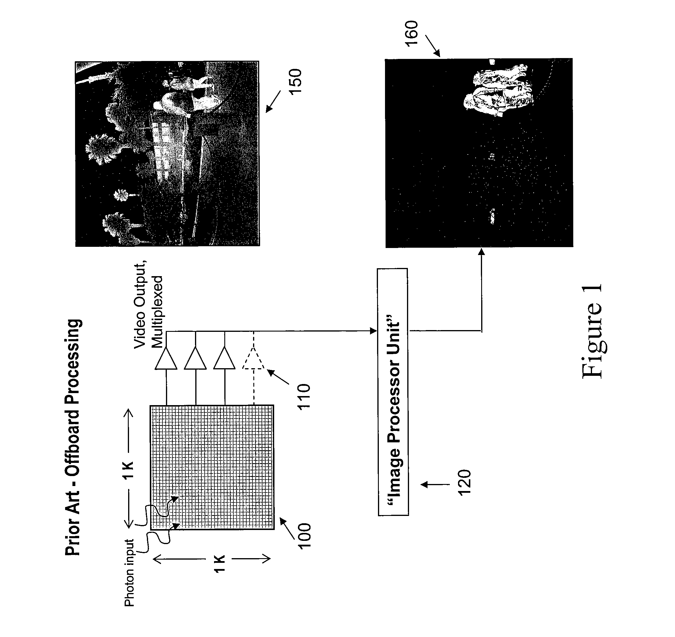
[0052]Referring now in more detail and by reference characters to the drawings which illustrate practical embodiments of the present invention, FIG. 1 designates a conventional, commercially available, prior art image processing system. In this case the imaging system in part contains an integrated circuit chip, which is identified by reference numeral 100, and typically has a pixel density of one thousand pixel size or greater in the X-axis and in the Y-axis, with each frame, that is a group of pixels which make-up a full frame at any point in time. There is no target detection and there is no attempt to detect a target object, in the image or even apart from the image.

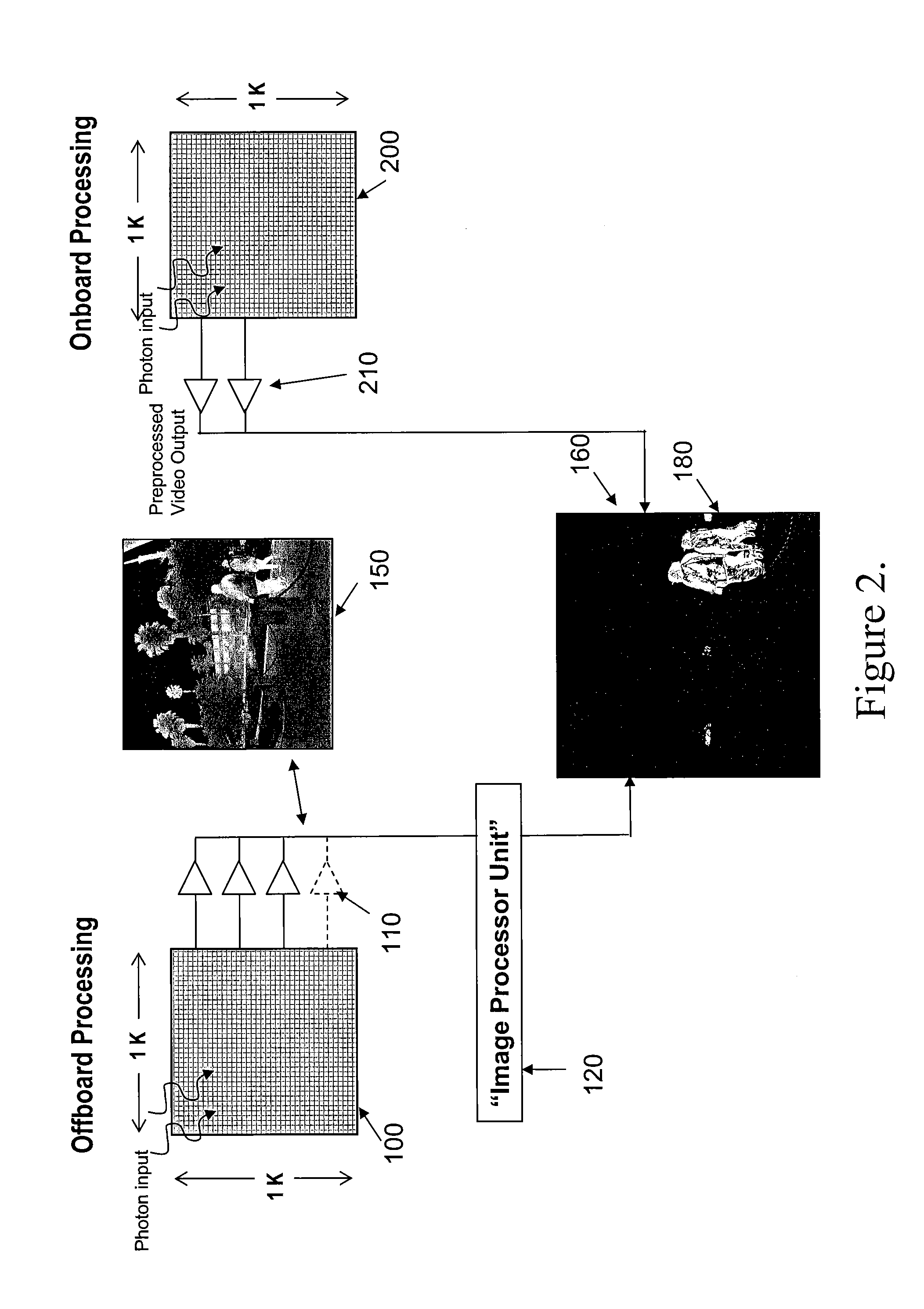
[0053]The circuit chip which contains the image sensors has outputs directed to an imaging processor 120, as hereinafter described in more detail. It can be observed that the outputs of the chip 100 are introduced through output amplifiers 110 and into the image processing unit 120. An output of the circuit chip itse...


PUM


Abstract

Detection of a target object or a characteristic of that object, e.g. temperature or movement in an image of a scene at a focal plane of the image and with processing of signals representative of the image occurring at that focal plane with a sensor and an integrated circuit processor on an imaging circuit chip used to record the scene. Moreover, processing of the signals representative of the image and the object or characteristic of the object can all be processed in parallel. This arrangement allows for filtering of objects with the ability to distinguish the object generating signals from background clutter. The incorporation of the entire circuit in this integrated circuit chip increases the compactness and efficiency. Moreover, all signal processing will occur at the focal plane eliminates the need for external processing electronics thereby increasing compactness and efficiency while reducing spatial noise.

Description

RELATED APPLICATIONS[0001]This application is based on and claims the benefit of and priority from my U.S. utility application Ser. No. 12 / 101,139, filed Apr. 10, 2008 which in turn claims the benefit and priority of provisional patent application Ser. No. 60 / 922,587 filed Apr. 10, 2007, for Automated Cuing Circuit for Image Sensors, the full contents of which are hereby incorporated herein by reference.GOVERNMENT RIGHTS[0002]The U.S. Government has a paid-up license in this invention and the right in limited circumstances to require the patent owner to license others on reasonable terms as provided for by the terms of Contract No. NAS1-20841 awarded by the USAF FA 8651-08-C-0 146.BACKGROUND OF THE INVENTION[0003]1. Field of the Invention[0004]This invention relates in general to automated sensing of an object or a characteristic of that object in or derived from an image of a scene and more particularly, to both a method and apparatus for sensing of target data associated with an o...

Claims


Application Information

Patent Timeline
Patent Type & Authority Patents(United States)
IPC IPC(8): G06K9/00H04N5/30H04N25/00
CPCH04N5/30H04N5/23245H04N5/378H04N5/217H04N5/335H04N23/81H04N23/667H04N25/00H04N25/78H04N25/75
Inventor CAULFIELD, JOHN
Owner CYAN SYST
Learn More