Pretreatment processes within a batch ald reactor

a batch ald reactor and pretreatment technology, applied in the field of fabrication processes, can solve the problems of reducing the overall fabrication throughput of ald process, affecting the quality of ald process,

Inactive Publication Date: 2008-10-23
APPLIED MATERIALS INC
View PDF99 Cites 441 Cited by
  • Summary
  • Abstract
  • Description
  • Claims
  • Application Information

AI Technical Summary

Problems solved by technology

As the geometries of electronic devices continue to shrink and the density of devices continues to increase, the size and aspect ratio of the features are becoming more aggressive.
However, an ALD process usually has a slower deposition rate than a comparable CVD process for depositing a material of similar composition.
Therefore, an ALD process that reduces the overall fabrication throughput may be less attractive than the comparable CVD process.
However, batch processes using CVD techniques remain limited due to the smaller geometries of modern devices.
Current batch deposition processes utilizing ALD techniques may have an incubation delay prior to the onset of a constant deposition rate.
Also, current ALD batch deposition processes may form high levels of particulates and other contaminants that end-up on the substrate surface.
Contaminated surfaces may further increase incubation delay, as well as cause defects within the deposited material that lead to poor device performance.

Method used


Image

  • Pretreatment processes within a batch ald reactor
  • Pretreatment processes within a batch ald reactor

Examples


example 1

HfO2 (H2O-Soak / O3-ALD)—

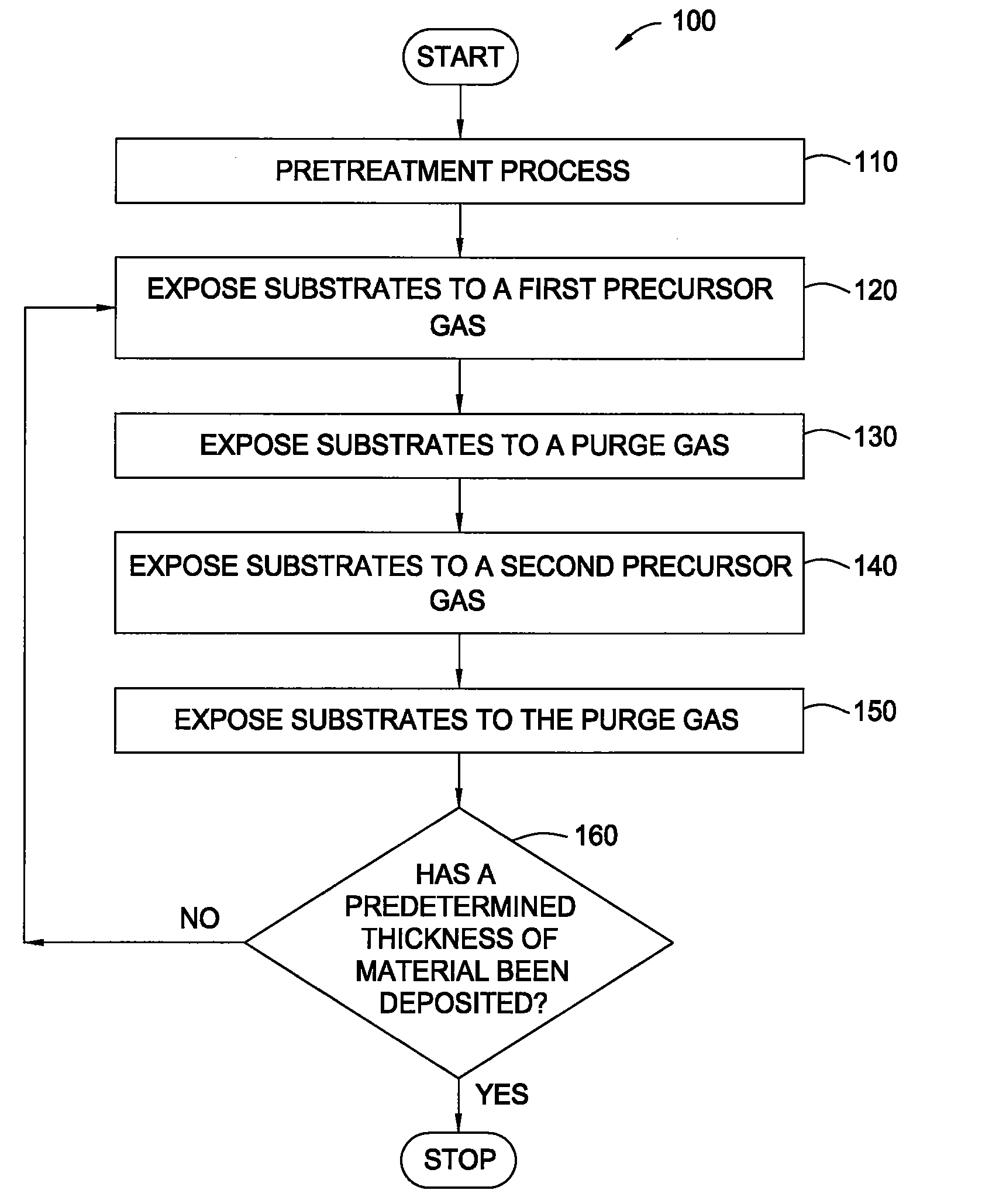
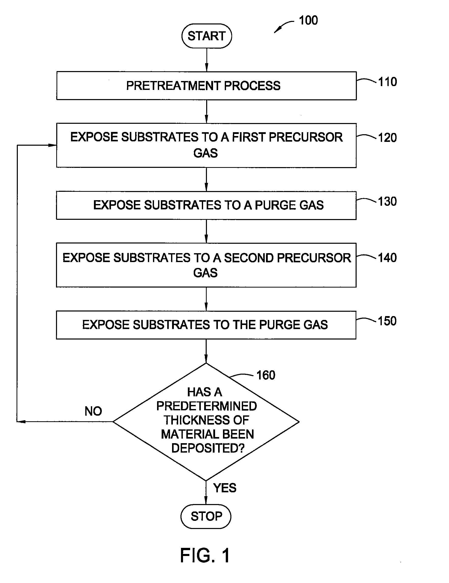
[0042]A batch of 50 substrates is positioned on the susceptors of a boat within the mini-batch ALD chamber. The process chamber is maintained at a pressure of about 8 Torr at about 250° C. and exposed to a pretreatment gas containing water vapor for about 20 minutes. Thereafter, a hafnium oxide layer is formed during an ALD process by sequentially exposing the substrates to a hafnium precursor (TDMAH in nitrogen carrier gas) and ozone (15 at % ozone in oxygen). The substrates are heated to about 250° C. and exposed to a plurality of ALD cycles. Each ALD cycle includes flowing TDMAH into the chamber for about 30 seconds, evacuating the chamber for about 30 seconds, flowing nitrogen (purge gas) into the chamber for about 30 seconds, evacuating the chamber for about 30 seconds, flowing ozone into the chamber for about 30 seconds, evacuating the chamber for about 30 seconds, flowing nitrogen into the chamber for about 30 seconds and evacuating the chamber for abou...

example 2

HfO2 (O3-Soak / H2O-ALD)—

[0043]A batch of 50 substrates is positioned on the susceptors of a boat within the mini-batch ALD chamber. The process chamber is maintained at a pressure of about 6 Torr at about 200° C. and exposed to a pretreatment gas containing ozone (15 at % ozone in oxygen) for about 5 minutes. Thereafter, a hafnium oxide layer is formed during an ALD process by sequentially exposing the substrates to a hafnium precursor (TDMAH in nitrogen carrier gas) and water vapor (in nitrogen carrier gas). The substrates are heated to about 200° C. and exposed to a plurality of ALD cycles. Each ALD cycle includes flowing TDMAH into the chamber for about 30 seconds, evacuating the chamber for about 30 seconds, flowing nitrogen (purge gas) into the chamber for about 30 seconds, evacuating the chamber for about 30 seconds, flowing water vapor into the chamber for about 30 seconds, evacuating the chamber for about 30 seconds, flowing nitrogen into the chamber for about 30 seconds and ...

example 3

HfSiO4 (O3-Soak / H2O-ALD)—

[0044]A batch of 50 substrates is positioned on the susceptors of a boat within the mini-batch ALD chamber. The process chamber is maintained at a pressure of about 8 Torr at about 300° C. and exposed to a pretreatment gas containing ozone (15 at % ozone in oxygen) for about 10 minutes. Thereafter, a hafnium silicate layer is formed during an ALD process by sequentially exposing the substrates to a hafnium precursor (TDMAH in nitrogen carrier gas), water vapor, a silicon precursor (Tris-DMAS in nitrogen carrier gas) and water vapor. The substrates are heated to about 300° C. and exposed to a plurality of ALD cycles. Each ALD cycle includes flowing TDMAH into the chamber for about 30 seconds, evacuating the chamber for about 30 seconds, flowing nitrogen (purge gas) into the chamber for about 30 seconds, evacuating the chamber for about 30 seconds, flowing water vapor into the chamber for about 30 seconds, evacuating the chamber for about 30 seconds, flowing n...


PUM


Abstract

Embodiments of the invention provide methods for forming a hafnium material on a substrate within a processing chamber. In one embodiment, a method is provided which includes exposing the substrate within the processing chamber to a first oxidizing gas during a pretreatment process, exposing the substrate sequentially to a second oxidizing gas and a deposition gas during an atomic layer deposition (ALD) cycle, wherein the second oxidizing gas contains water and the deposition gas contains a hafnium amino compound, and repeating the ALD cycle to form a hafnium-containing layer having a thickness within a range from about 5 Å to about 300 Å. In one example, the first oxidizing gas contains an O3 / O2 mixture having an ozone concentration within a range from about 5 atomic percent to about 30 atomic percent.

Description

CROSS-REFERENCE TO RELATED APPLICATIONS[0001]This application is a continuation of U.S. Ser. No. 11 / 213,161 (APPM / 010038), filed Aug. 26, 2005, which is herein incorporated by reference in its entirety.BACKGROUND OF THE INVENTION[0002]1. Field of the Invention[0003]Embodiments of the invention generally relate to fabrication processes, and more specifically, for treatment processes and deposition processes while forming a material on a substrate.[0004]2. Description of the Related Art[0005]In the field of semiconductor processing, flat-panel display processing or other electronic device processing, vapor deposition processes have played an important role in depositing materials on substrates. As the geometries of electronic devices continue to shrink and the density of devices continues to increase, the size and aspect ratio of the features are becoming more aggressive. Feature sizes of about 45 nm or smaller and aspect ratios of 10, 20, 30 or greater are more frequently desired dur...

Claims


Application Information

Patent Timeline
Patent Type & Authority Applications(United States)
IPC IPC(8): H01L21/31
CPCC23C16/0218C23C16/405C23C16/45531C23C16/45546H01L21/3141H01L21/3142H01L21/02181H01L21/0228
Inventor MAHAJANI, MAITREYEE
Owner APPLIED MATERIALS INC
Why Eureka
Try Eureka