High power wireless resonant energy transfer system

a wireless resonant energy and wireless technology, applied in the direction of capacitor propulsion, battery/fuel cell control arrangement, transportation and packaging, etc., can solve the problems of high energy consumption, multiple recharges, and inefficient centralized energy production

Inactive Publication Date: 2008-10-30
FARKAS
View PDF7 Cites 428 Cited by
  • Summary
  • Abstract
  • Description
  • Claims
  • Application Information

AI Technical Summary

Benefits of technology

[0007]One aspect of the invention provides a high power wireless resonant energy transfer system, comprising an energy transmission system that is arranged to wirelessly transfer energy across an airgap. An energy reception system is positioned to receive the transferred energy across the airgap through a resonant inductive coupling between the transmission and reception system. The energy transmission system is arranged to automatically and electronically vary the spatial direction of the resonant inductive coupling with the alignment between the transmission and reception system, such that energy transfer occurs at a desired location, frequency and power level.
[0008]Another aspect of the invention provides a combined heat and power generation, comprising a local energy generation system that is arranged to generate and provide electrical energy for a local site and for an electrically chargeable vehicle in proximity to the local site, used in conjunction with the previously described high power wireless resonant energy transfer system.
[0009]Another aspect of the invention provides a method to wireless e...

Problems solved by technology

The centralized production of energy itself can be both inefficient (with only ˜30-35% efficiency) and highly polluting.
Additionally, most of the fossil fuels used for electric power generation produce waste heat at the power plants and in the transmissio...

Method used


Image

  • High power wireless resonant energy transfer system
  • High power wireless resonant energy transfer system
  • High power wireless resonant energy transfer system

Examples


Embodiment Construction

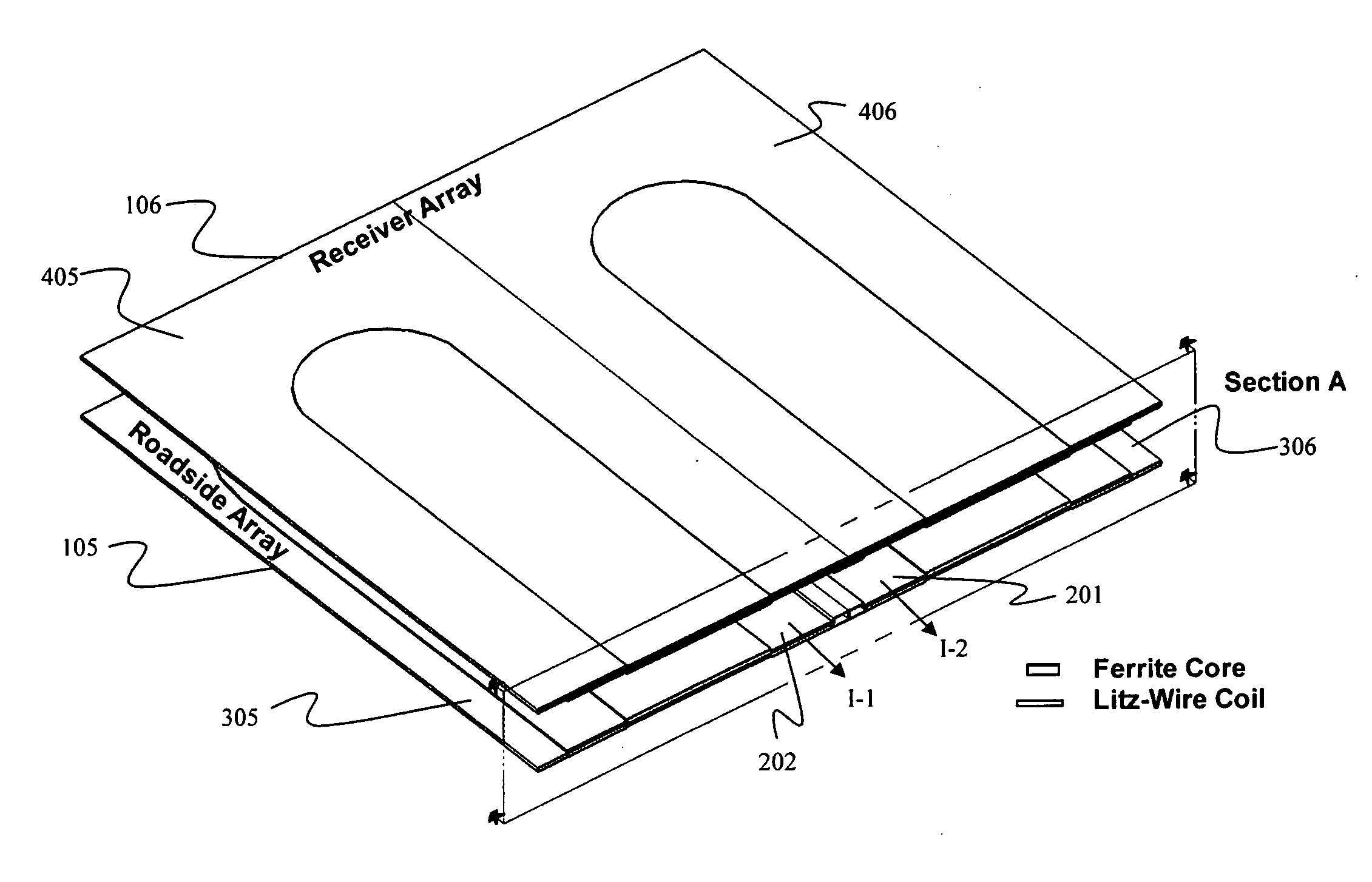
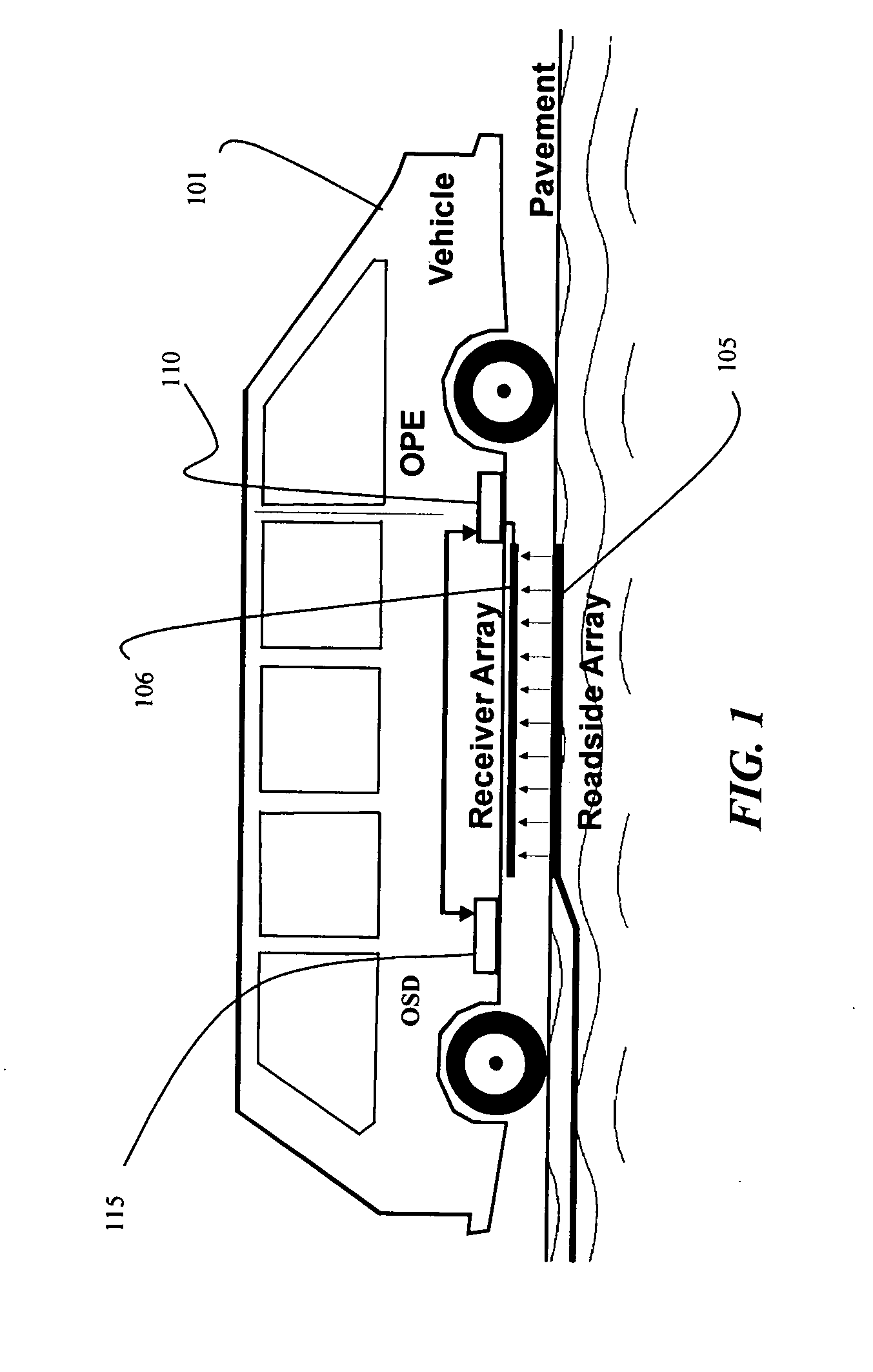
[0031]FIG. 1 illustrates one embodiment of a high power wireless resonant energy transfer system. This embodiment includes an energy transmission system 105 for wirelessly transmitting energy to an energy reception system 106 when the transfer system is activated.

[0032]The energy transmission system 105 is preferably disposed beneath a roadway surface, although transmission systems disposed on the surface are contemplated as well. The energy reception system 106 is preferably disposed on the undercarriage of a vehicle 101, which uses the transferred electrical power to either charge an onboard energy storage device unit 115 or for propulsion / use directly. The storage unit 115 typically includes a set of batteries and / or capacitors which store the energy until it is needed by the vehicle for propulsion. This storage and use is typically controlled by onboard power electronics 110. Although FIG. 1 shows a particular arrangement of this embodiment, other arrangements are also possible....


PUM


Abstract

A high power wireless resonant energy transfer system transfers energy across an airgap.

Description

[0001]This application claims the benefit of provisional application No. 60 / 854,673 to Farkas filed on Oct. 25, 2006.BACKGROUND OF THE INVENTION[0002]1. Field of the Invention[0003]This invention relates to a high power wireless resonant energy transfer system.[0004]2. Description of the Related Art[0005]Traditional electrical energy sources used to power vehicles and buildings typically rely on centralized production and a long-distance redistribution network of transmission lines to provide electrical energy to consumers. The centralized production of energy itself can be both inefficient (with only ˜30-35% efficiency) and highly polluting. Additionally, most of the fossil fuels used for electric power generation produce waste heat at the power plants and in the transmission lines. This heat can lost to the environment.[0006]Although electric vehicles may help offset some of this pollution, as well as pollution caused by their gasoline counterparts, such vehicles must typically re...

Claims


Application Information

Patent Timeline
IPC IPC(8): H01F38/00
CPCB60L11/005Y02T90/121B60L11/182B60L11/1844B60L11/1887B60L2200/28B60L2200/36H02J5/005H02J7/025Y02E20/14Y02T10/7022Y02T10/7094Y02T90/122Y02T90/128Y02T90/14Y02T90/163Y02T90/34Y04S10/126Y02E60/721B60L2200/26B60L11/16Y02T10/7072H01F38/14B60L50/40B60L50/30B60L53/63B60L58/40H02J7/0042H02J7/34H02J1/16B60L53/122B60L53/126Y02E60/00Y02T10/70Y02T90/12H02J50/402H02J50/90H02J50/12H02J50/70Y02T90/16Y02T90/40
Inventor FARKAS, LASZLO
Owner FARKAS
Why Eureka
Try Eureka