Class G motor drive

a motor drive and motor technology, applied in the direction of dc motor rotation control, power amplifiers, amplifiers, etc., can solve the problems of high frequency switching noise that can interfere with the operation of the device, employ these approaches, and achieve the effect of improving the efficiency of the motor drive, reducing power dissipation, and reducing high frequency switching nois

Inactive Publication Date: 2008-10-30
ACU TECH SEMICON
View PDF16 Cites 30 Cited by
  • Summary
  • Abstract
  • Description
  • Claims
  • Application Information

AI Technical Summary

Benefits of technology

The present invention aims to improve the efficiency of a VCM driver by using PWM or PSM switching approaches. However, these approaches introduce high frequency switching noise that can interfere with the operation of the device. The manufacturers of Hard Disk Drives are reluctant to employ these approaches despite their advantages in terms of reduced power dissipation.

Problems solved by technology

The technical problem addressed in this patent text is to improve the efficiency and accuracy of motor drives in hard disk drive and data storage devices. The current is wasted during the acceleration and deceleration phases of the motor, and the use of PWM and PWM systems can result in high levels of interference and distortion. The solution proposed is a class G amplifier that uses an unipolar approach and a unique method of driving the motor. The invention aims to reduce the sources of electrical noise, improve the dynamic range of the motor, and avoid the introduction of high side effects.

Method used


Image

  • Class G motor drive
  • Class G motor drive
  • Class G motor drive

Examples


Embodiment Construction
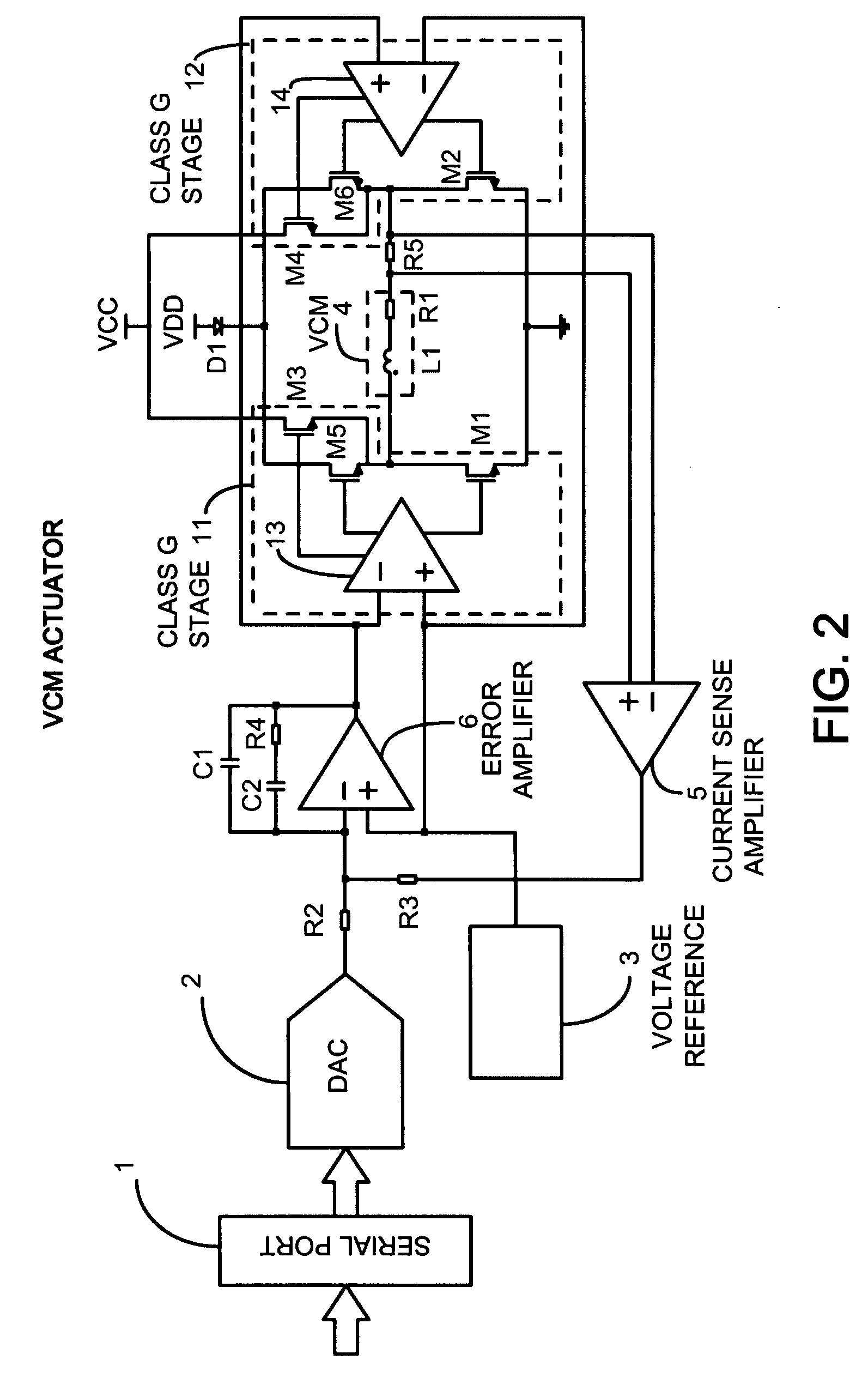
A. FIG. 2

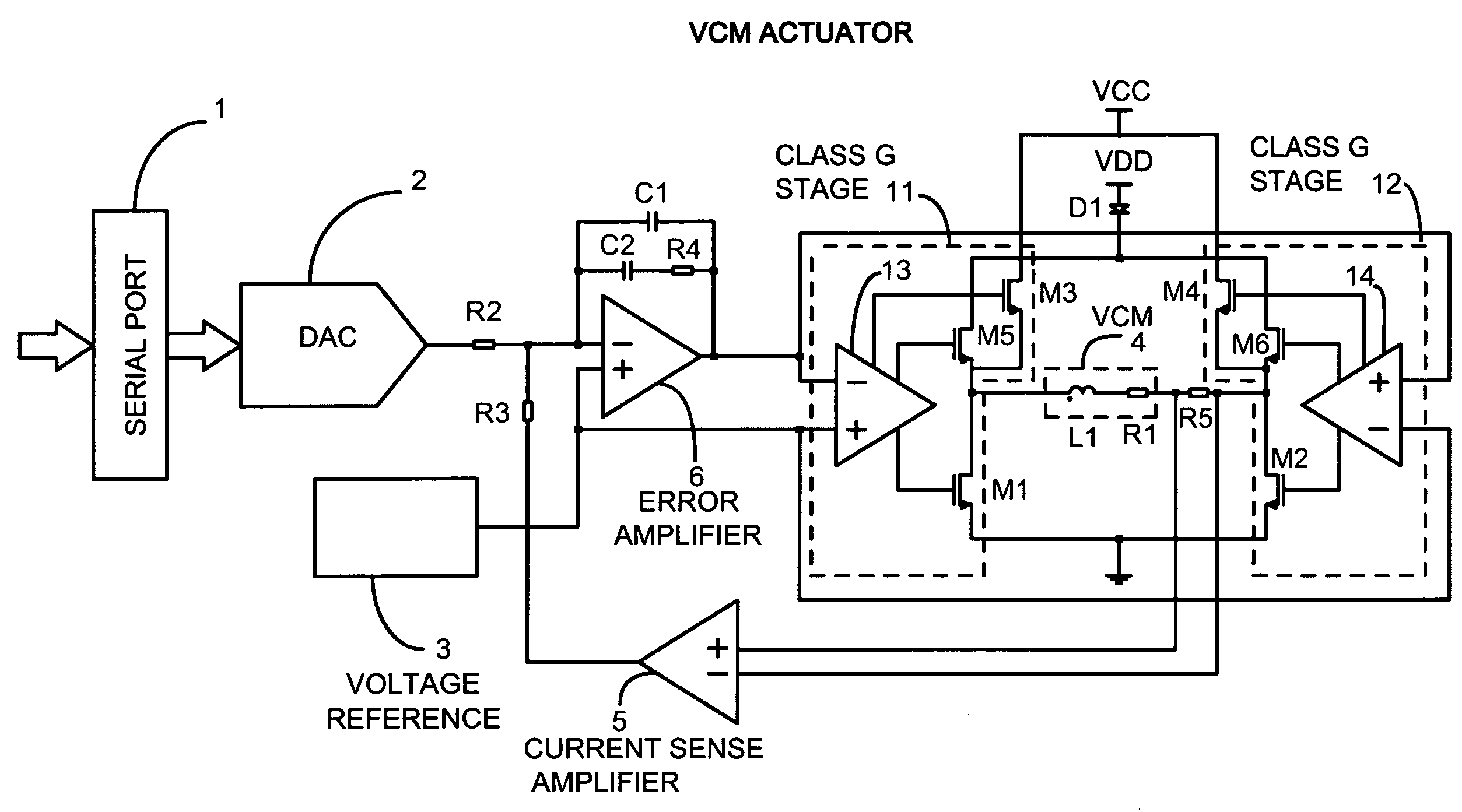
[0071]FIG. 2 shows a general embodiment for the basic VCM driver control system utilizing two Class G stages 11 and 12. The blocks 13 and 14 drive the gates of the low side power transistors M1 and M2, the gates of the high side power transistors M3 and M4 electrically coupled to the higher voltage power supply designated as VCC, and the gates of the high side power transistors M5 and M6 electrically coupled to the lower voltage power supply designated as VDD through the series diode D1.

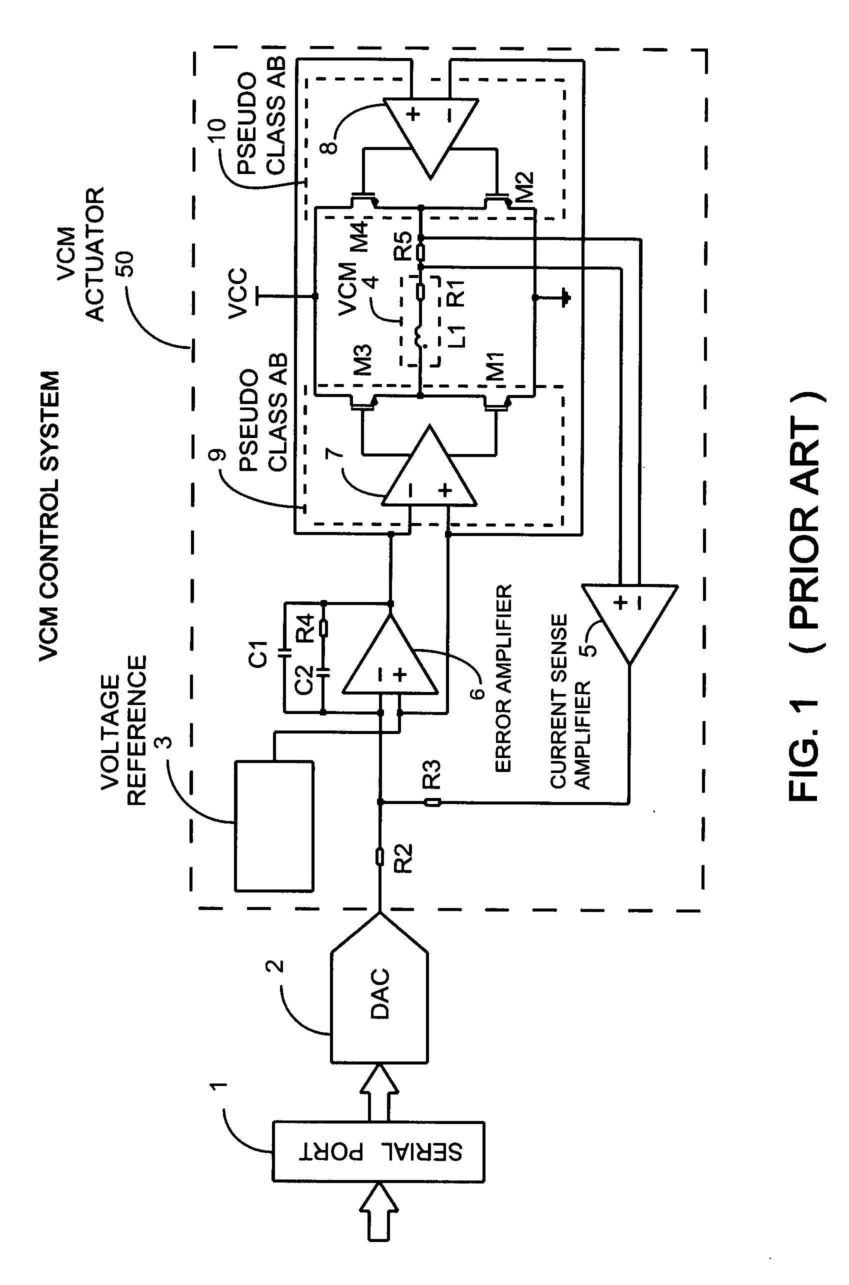
[0072]The embodiment of FIG. 2 is very similar to the classical implementation of the prior art described in FIG. 1, since there is an inner current control loop that regulates the load current sensed as the voltage drop on the resistor R5 and amplified by the operational amplifier 5. An error amplifier 6 drives the output power stage and operates to null the error signal defined as difference between the output of the sense amplifier 5 and the output of the DAC 2 whose input is fed by the s...


PUM


Abstract

A method for driving a motor by using an output stage amplifier that operates between two or more separate supply voltages, depending on the amplitude of the input signal, is presented. This bridge unipolar class G stage allows driving the motor with high accuracy and improved efficiency without introducing switching noise typical of PWM motor driving. This method can be applied with the same benefits to class AB, pseudo class AB or to class A output stages. When this method is associated with an imposed current driving approach and with a current oversampling digital to analog converter the resulting advantages are very significant.

Description


Claims


Application Information

Patent Timeline
Owner ACU TECH SEMICON
Why Eureka
Try Eureka