
Object-clamping lid subassembly of a test socket for testing electrical characteristics of an object

a technology for testing electrical characteristics and objects, which is applied in the direction of electrical testing, measurement devices, instruments, etc., to achieve the effects of uniform pressure, simple construction and assembly, and low manufacturing cos

Inactive Publication Date: 2008-10-30
PROTOS ELECTRONICS
View PDF10 Cites 3 Cited by
  • Summary
  • Abstract
  • Description
  • Claims
  • Application Information

AI Technical Summary

Benefits of technology

[0019]It is an object of the present invention to provide a lid subassembly that is intended for use in testing electrical characteristics of contats, e.g., in a bump connectivity test socket for testing electronic devices such as IC chips, and that is simple in construction and assembly, inexpensive to manufacture, and provides uniform application of pressure from the pusher to the object without the use of complicated self-alignment means. It is another object of the invention to provide a test socket lid subassembly in which a pusher is separated from the lid subassembly during pivotal movement of the latter. It is another object to provide a test socket of the aforementioned type wherein the pusher is connected to a rotating handle and is inserted into the lid subassembly in the direction perpendicular to the pressure-receiving surface of the test object after the lid is fixed in an object-locking position.
[0022]When the handle rotates together with the thread ring relative to the lid member, its lobe, which projects in the radial outward direction, also turns, and when movement of the thread ring, and hence, of the handle is stopped because of contact of the end face of the thread ring with the object, the aforementioned lobe is positioned just above the latch. As a result, the latch is interlocked in the locked position and cannot be accidentally unlocked until the thread ring is untwisted from the object clamping position. In other words, when the object is clamped, the lid cannot be accidentally opened.
[0023]Since IC chips may have different heights, the device of the invention has a feature that allows adjustment of the vertical stroke of the pusher relative to the object. This is achieved by forming a plurality of circumferentially arranged threaded openings on the upper end-face of the thread ring, while the handle has a plurality of openings for inserting the screws that attach the handle to the thread ring. By locking the handle in different positions with respect to the beginning of the thread grooves on the outer surface of the thread ring, it becomes possible to adjust the total angle of rotation of the pusher relative to the lid member from the beginning of the rotation to the moment of contact of the pusher with the object.

Problems solved by technology

As a result, the latch is interlocked in the locked position and cannot be accidentally unlocked until the thread ring is untwisted from the object clamping position.

Method used


Image

  • Object-clamping lid subassembly of a test socket for testing electrical characteristics of an object
  • Object-clamping lid subassembly of a test socket for testing electrical characteristics of an object
  • Object-clamping lid subassembly of a test socket for testing electrical characteristics of an object

Examples


Embodiment Construction

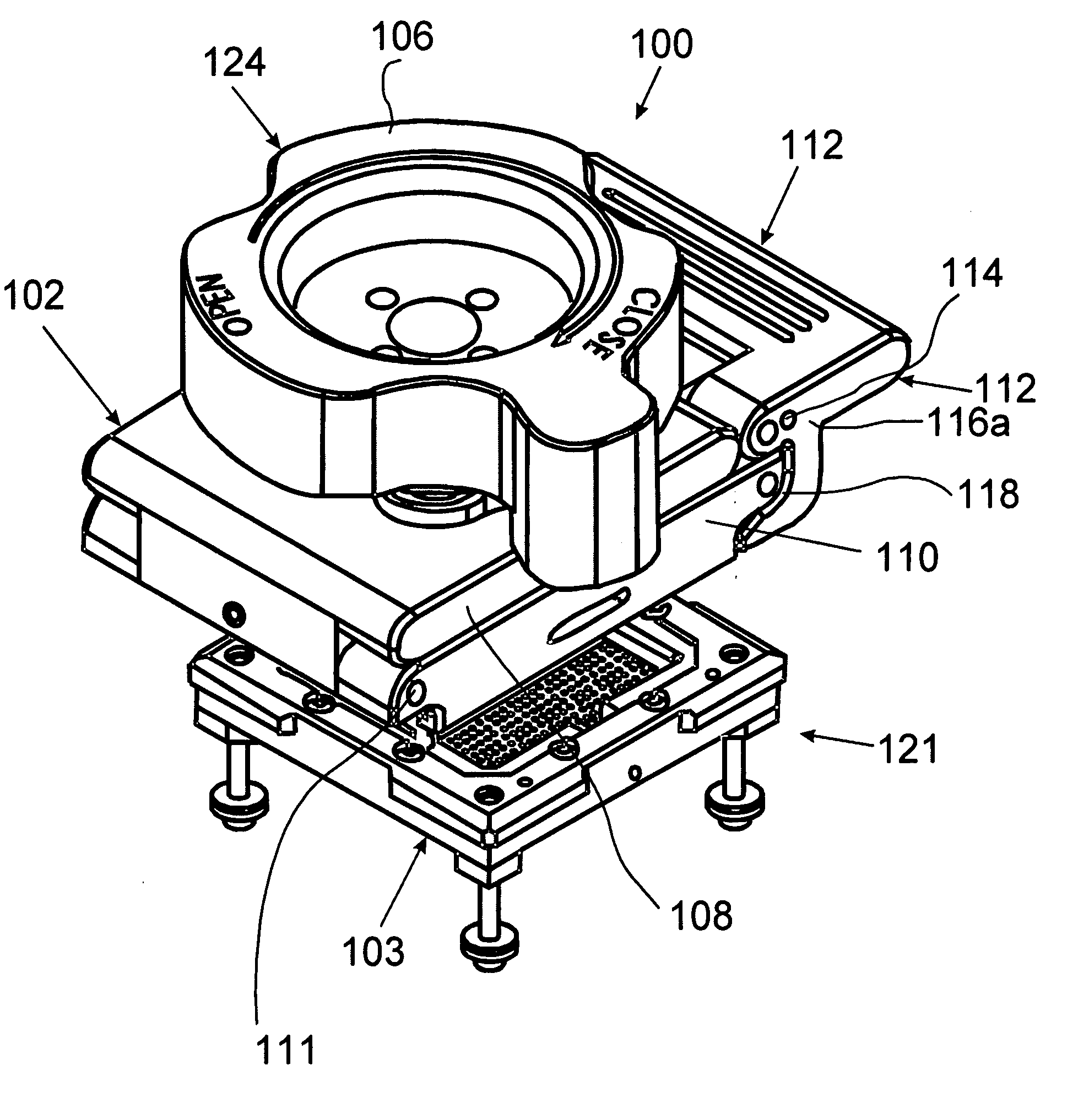
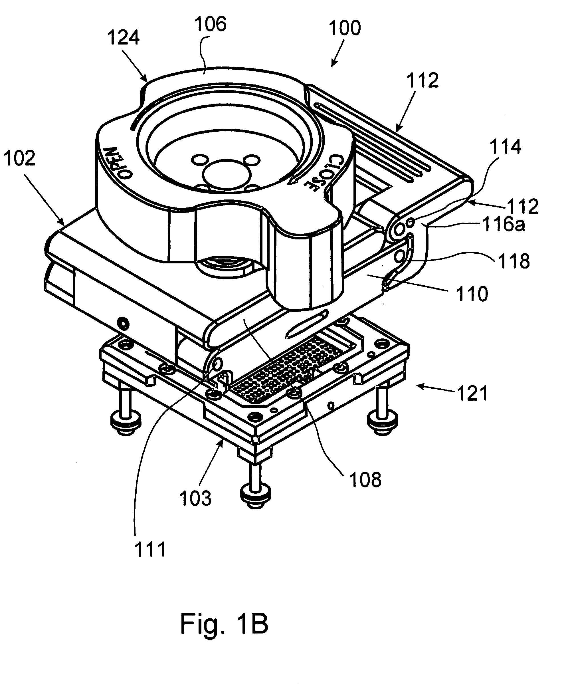
[0034]A general three-dimensional view of the test-socket lid subassembly of the invention in the closed position is shown in FIG. 1B. The lid subassembly, which as a whole is designated by reference numeral 100, consists of two separated main parts, i.e., a lid 102 for locking the object in the socket unit 103 and a pusher 124 with a handle 106 for clamping the object in the locked position. FIG. 1C is a bottom view of the lid subassembly.

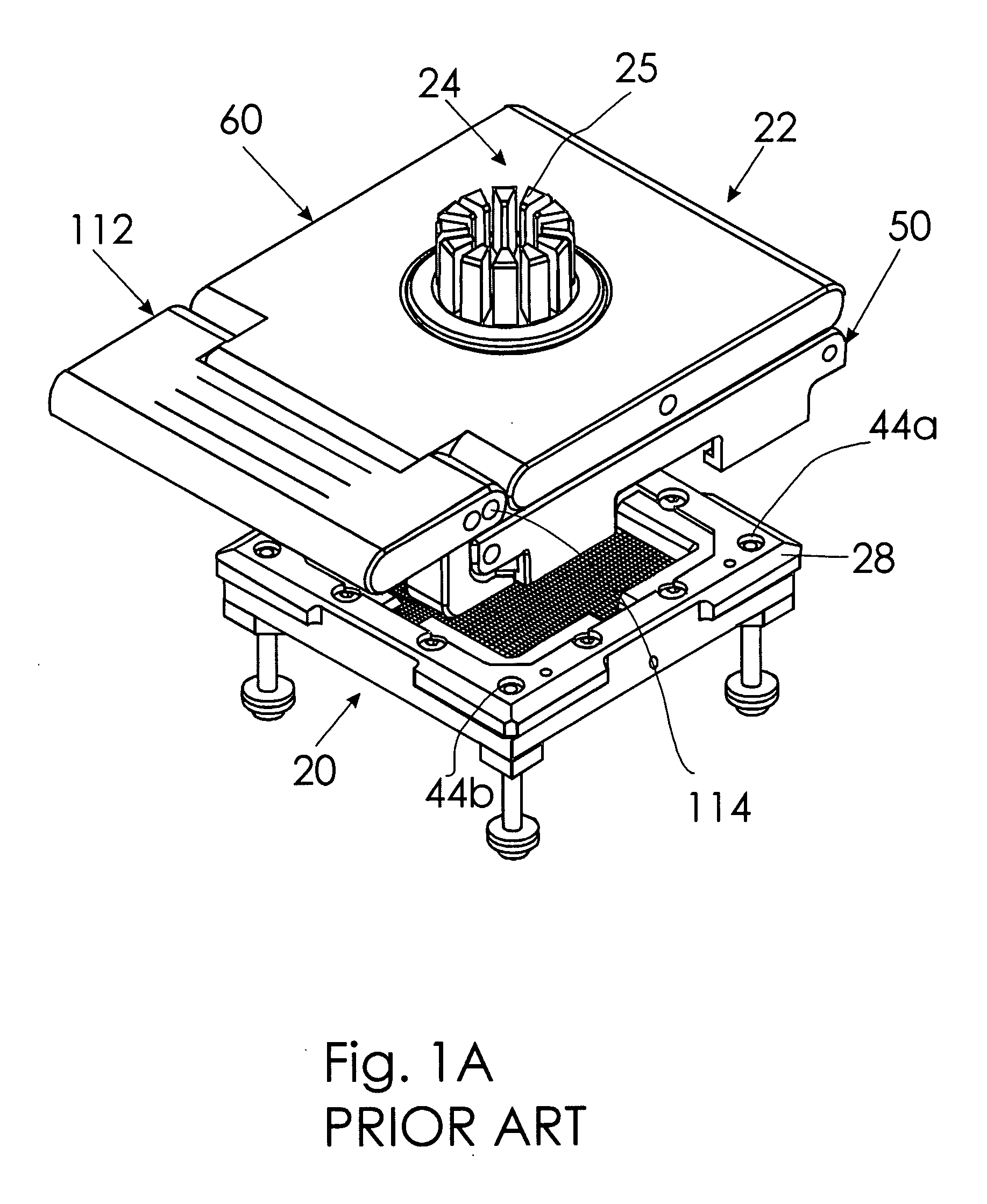
[0035]Similar to the above-described device of U.S. patent application Ser. No. 11 / 490,276, the lid subassembly has a lid member 108, one end of which is pivotally connected to a lid frame 110 with rotation around a transverse axle 111, while the opposite end of the lid member 108 (FIG. 1B) pivotally supports a latch 112 that can be turned on an axle 114 and locked around the outer rings of the bearings 107 and 109 (FIG. 1C) installed on the edge of the lid frame 110 for locking the lid member 108 to the frame 110. For this purpose, the latch 112 ...


PUM


Abstract

The test-socket lid subassembly of the invention consists of a lid for locking the object in the socket unit and a pusher with a handle for clamping the object in the locked position. The pusher is separated from the lid and is inserted into the lid for pressing on the object to fix the latter in the socket only after the lid is locked in place. The pusher is made in the form of a threaded ring, which has an outer thread for engagement with the inner thread in the central opening of the lid member for movement in the direction perpendicular to the contact surface of the object. This provides uniform distribution of pressure on the test object that is locked in the socket subassembly.

Description

FILED OF THE INVENTION[0001]The present invention relates in general to the field of semiconductor product testing and, more particularly, to test sockets used for testing electrical characteristics of objects, e.g., for testing bump connectivity to bond pads in the manufacture of semiconductor chips. More specifically, the invention relates to a lid subassembly that is used in test sockets for locking a test object in a working position for testing and for supporting a pusher that applies clamping pressure to the test object during the test.BACKGROUND OF THE INVENTION[0002]In manufacturing, all semiconductor devices pass through the following three essential stages: wafer fabrication, assembly of fabricated dies into semiconductor chips, and testing of semiconductor chips. The semiconductor chips are then incorporated into respective PC boards, and the assembled PC boards are also subjected to testing. The testing stage always includes evaluation of the electrical connections withi...

Claims


Application Information

Patent Timeline
Patent Type & Authority Applications(United States)
IPC IPC(8): G01R31/02
CPCG01R1/0466G01R1/0483
Inventor WOODEN, GREGG
Owner PROTOS ELECTRONICS
Learn More